12
ENGLISH
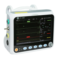
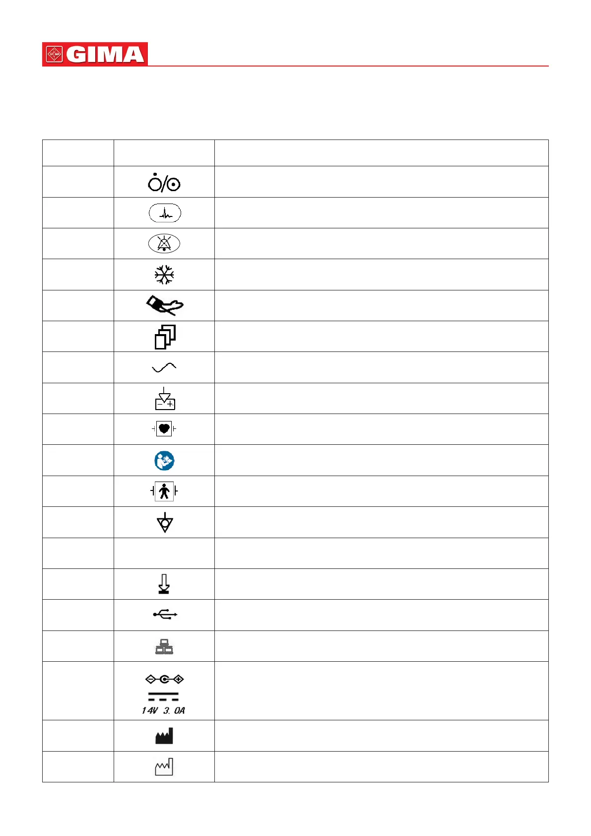
1.2 Equipment Symbols
1.2.1 Symbol/Icon on the Device
Item Symbol/Icon Descripon
1 Power switch
2 ECG lead key
3 Alarm Silence key
4 Freeze/ Unfreeze key
5 Start/Cancel NIBP measurement
6 Display view key
7 AC power indicator
8 Working power supply indicator
9 Type CF applied parts with debrillaon-proof
10 Warning --- refer to User Manual
11 Type BF applied parts with debrillaon-proof
12 Equipotenal grounding terminal
13 SN Serial number
14 Baery cover
15 USB data cable connector (used for data upload)
16 Network interface (used for connecng to Central Monitoring System)
17
Icon of DC power supply socket with polarity indicaon.
DC Power supply socket indicaon with rated voltage and current.
18 Manufacturer
19 Manufacturing date