6-22
For the GPU module to take effect, make sure processor 2 of the compute module is in position.
Procedure
The procedure is the same for installing GPU modules GPU-P4-X, GPU-P40-X, GPU-T4, GPU-P100,
GPU-V100, and GPU-V100-32G. This section uses the GPU-P100 as an example.
To install a GPU module in a compute module:
1. Power off the server. For more information, see "Powering off the server."
2. Remove the
security bezel, if any. For more information, see "Replacing the security bezel."
3. Remove the compute module. For more information, see "Removing a compute module."
4. Remove the compute module access panel. For more information, see "Replacing a compute
module a
ccess panel."
5. Remove the high mid air baffle. For more information, see "Replacing air baffles in a compute
module."
6. Install the GPU module air baffle to the compute module. For more information, see "Installing
the low mid ai
r baffle or GPU module air baffle to a compute module."
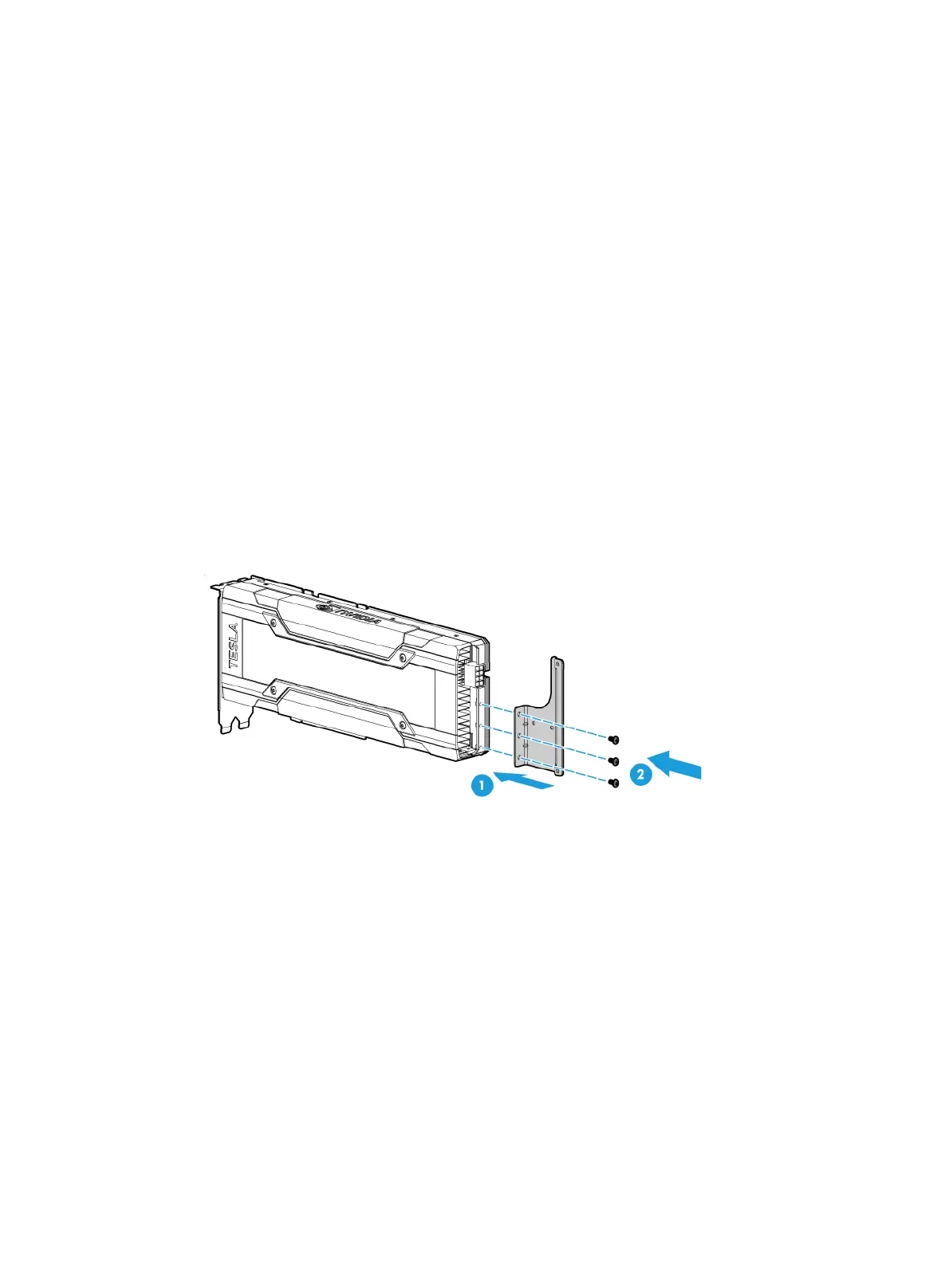
7. If the GPU module is dual-slot wide, attach the support bracket provided with the GPU module
to the GPU module. As shown in Figure 6-28, ali
gn screw holes in the support bracket with the
installation holes in the GPU module. Then, use screws to attach the support bracket to the
GPU module.
Figure 6-28 Installing the GPU module support bracket
8. Install the GPU module and connect the GPU power cord:
a. Hold and rotate the latch upward to open it. For more information, see "Installing a riser card
and a PCIe m
odule in a compute module."
b. Connect the riser power end of the power cord (P/N 0404A0UC) to the riser card, as shown
by callout 1 in Figure 6-29.
c. Insert the
GPU module into PCIe slot 1 along the guide rails, as shown by callout 2 in Figure
6-29.
d. Con
nect the other end of the power cord to the GPU module and close the latch on the riser
card, as shown by callouts 3 and 4 in Figure 6-29.

 Loading...


