Operating Instructions • Thermal Transfer Printer TT4030 • 06-2017 • 031-93478
Operation
14
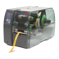
6.3 Setting the head locking system
The printhead is pressed on by two plungers. The
position of the two plungers must be adapted to the
width of the utilised material to
• achieve uniform print quality across the entire material
width,
• avoid wrinkles in the colour ribbon feed,
• prevent premature wear of the print roller and the
printhead.
1
2
3
Set the head locking system.
1 Grub screw
2 Plunger
3 Printhead locking lever
1 Loosen the grub screws of the two plungers using the
Allen key and adjust the two plungers to the width of
the material.
2 Turn the lever clockwise to lock the printhead.
3 Tighten the threaded pins.
4 Apply pressure on the printhead with the two plungers,
whose basic position is in the middle of the printhead
retainer.
; The head locking system is set.
This setting can be used for all applications.
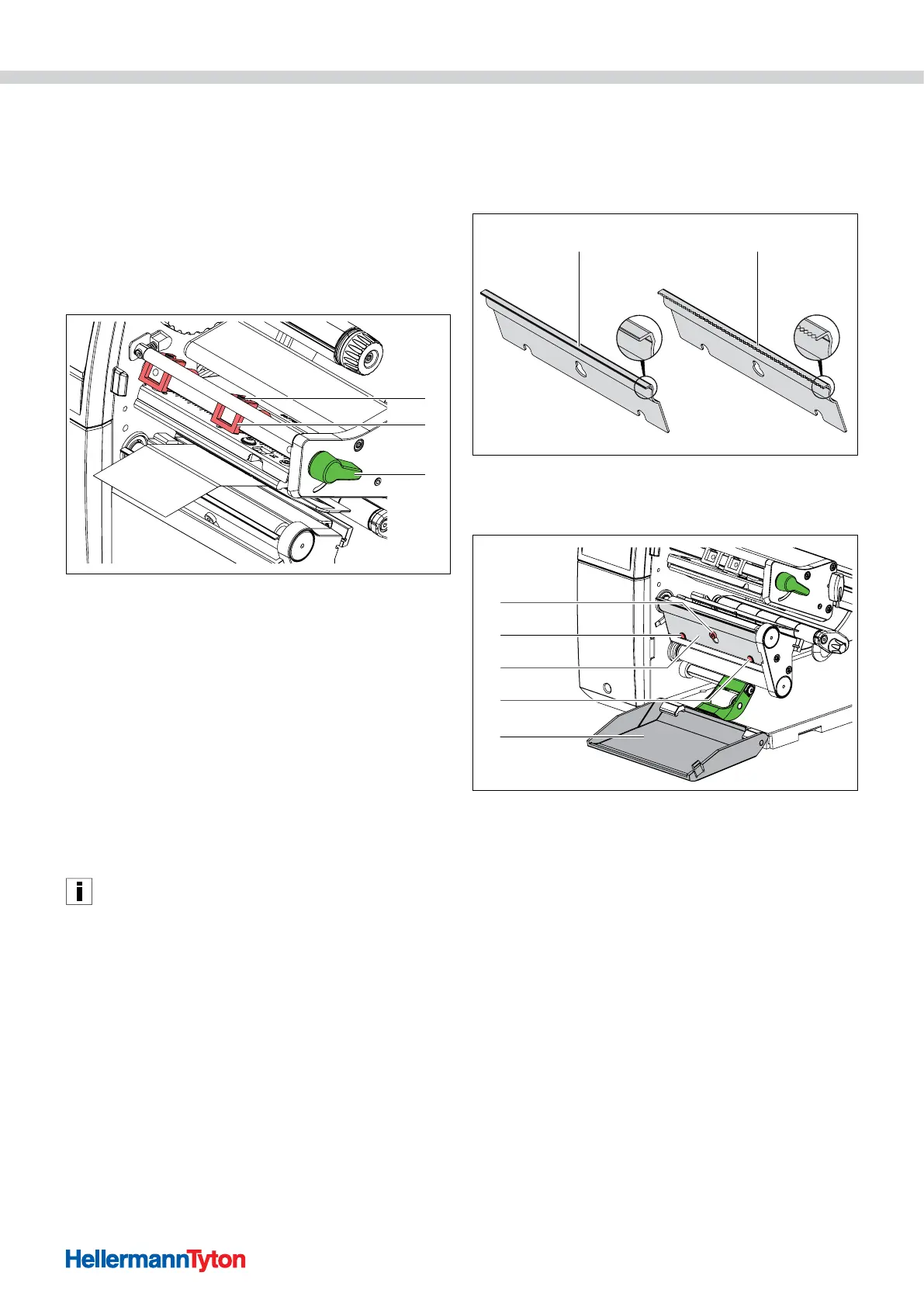
6.4 Installing or removing the dispensing or tear-off
plate
To convert the device for a different operating mode, a
dispensing plate or tear-off plate must be installed if
necessary.
1 2
Dispensing plate or tear-off plate.
1 Dispensing plate (only included with the dispenser version)
2 Tear-off plate
4
2
3
2
1
Installing and removing the dispensing plate or tear-off plate.
1 Screw
2 Pin
3 Plate
4 Cover
1 Remove the plate.
f Open the cover.
f Loosen the screw by several turns.
f Push the plate upwards.
f Remove the plate.
; The plate is removed.
2 Install the plate.
f Insert the plate on the screw.
f Push the plate down behind the pin.
f Tighten the screw.
; The plate is installed.
 Loading...