Operating Instructions • Thermal Transfer Printer TT4030 • 06-2017 • 031-93478
Technical Specifications
24
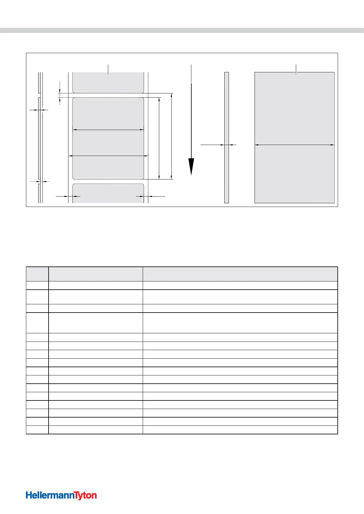
12.2 Sections/continuous material dimensions
QE/QS
(A)
E
F
DL
(DR)
B
C
HV
GE/GS
1 32
Sections/continuous material dimensions.
1 Materials
2 Feed direction
3 Continuous material/heat-shrink tubing
With small and thin materials or strong adhesives, there can be limitations. Critical uses must be tested and approved.
f Observe the bending stiffness The material must be able to follow the print roller.
Dimen-
sion
Designation Dimension in mm
B Material width 4 - 110
H
Material height
in dispensing mode
4 - 2000
12 - 200
- Tear-off length > 30
-
Cut length
with cutter
with perforation cutter
> 5
> 5
- Perforation length > 2
A Material distance > 2
C Wide carrier material 9 - 114
GE Continuous material width 4 - 114
GS Wide heat-shrink tubing 4 - 85
DL Left margin ≥ 0
DR Right margin ≥ 0
E Material thickness 0.03 - 0.60
F Carrier material thickness 0.03 - 0.13
QE Continuous material thickness 0.05 - 0.50
QS Heat-shrink tubing thickness ≤ 1.1
V Feed > 6
 Loading...