Operating Instructions • Thermal Transfer Printer TT4030 • 06-2017 • 031-93478
Technical Specifications
26
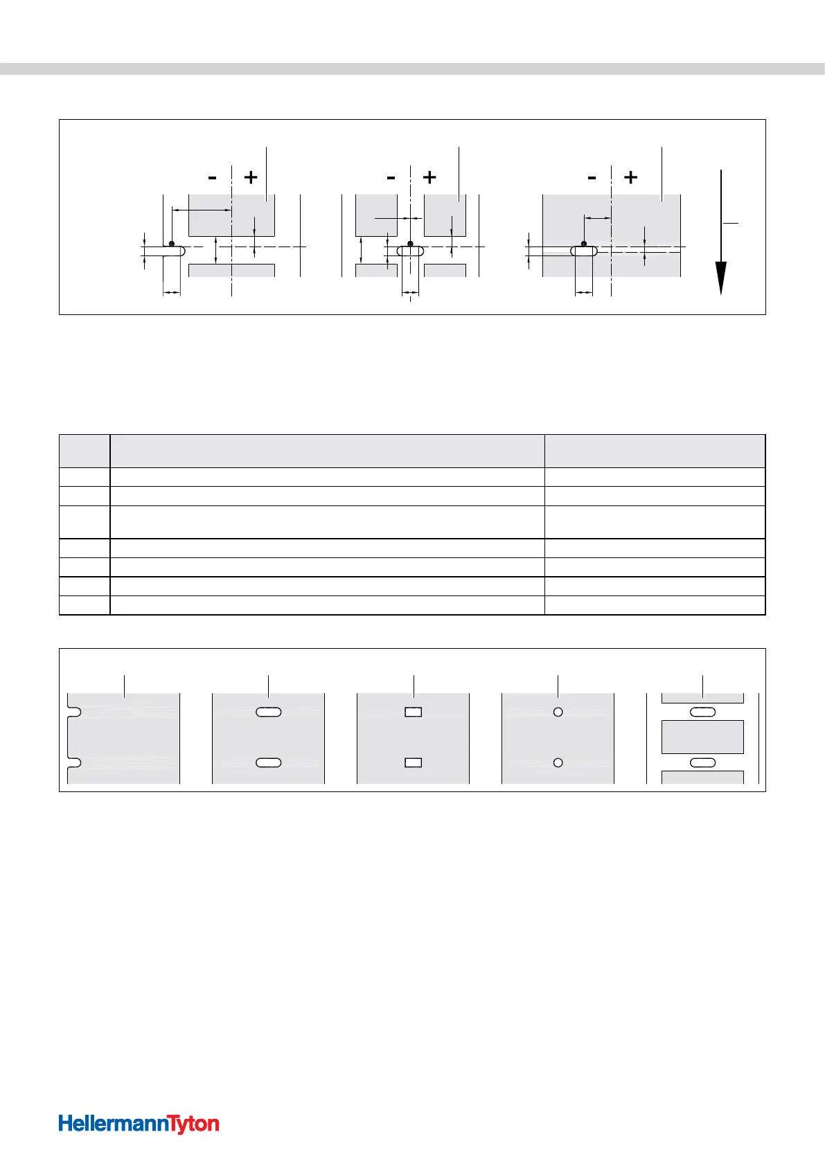
12.4 Dimensions for perforations
NN
N
YYY
PPP
TT4030
XM
XM XM
AZ
ZZ
AA
1 1 2
3
Dimensions for perforations.
1 Materials with perforations
2 Continuous material with perforations
3 Feed direction
For margin perforations: Minimum thickness of the carrier material 0.06 mm
Dimen-
sion
Designation Dimension in mm
A Material distance > 2
AZ Print zone distance > 2
N
Width of the perforation
for margin perforation
> 5
> 8
P Height of the perforation 2 - 10
XM Distance perforation - centre of paper feed -53 - ±0
Y Material start determined by the sensor through backlight detection Rear edge of the perforation
Z Distance determined material start - actual material start 0 to A - P
1 2 3 4 5
Examples for perforations.
1 Margin perforation
2 Slot perforation
3 Square perforation
4 Circular perforation (not recommended!)
5 Perforation between materials (not recommended!)
 Loading...