Home
Hisun
Offroad Vehicle
HS800UTV
Page 149
Hisun HS800UTV - Page 149
362 pages
Manual
Save Page as PDF
To Next Page
To Next Page
To Previous Page
To Previous Page
Loading...
E
N
G
I
N
E
- 135 -
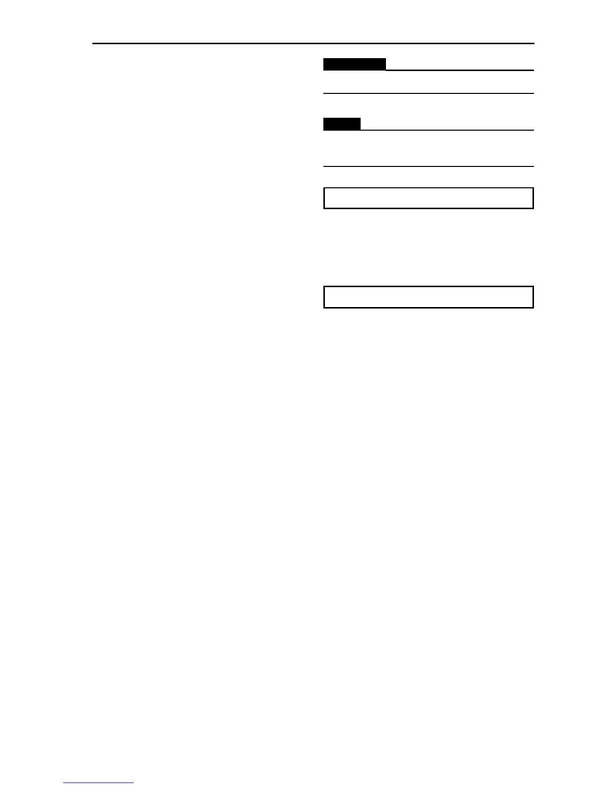
WARNING
:
A
lways use a new gasket.
NOTE
:
The “UP” mark on the timing chain tensione
r
should face up.
Timing chain tensioner bolt (10 Nm)
d. Remove the screwdriver, make sure that the
timing chain tensioner rod releases, and
tighten the cap bolt to
the specified torque.
Timing chain tensioner cap bolt (7 Nm)
148
150
Table of Contents
Main Page
Default Chapter
2
Table of Contents
2
Chapter 1 General Information
15
Watnings , Cautions and Notes
15
Description
16
Identification Code
17
Frame no
17
Engine no
17
Safety
18
Handing Gasoline Safely
18
Cleaning Parts
19
Warning Labels
19
Serial Numbers
20
Fasteners
20
Torque Specifications
20
Self-Locking Fasteners
20
Washers
20
Cotter Pins
21
Snap Rings and E-Clips
21
Shop Supplies
22
Lubricants and Fluids
22
Engine Oils
22
Greases
22
Brake Fluid
23
Coolant
23
Cleaners, Degreasers and Solvents
23
Gasket Sealant
23
Gasket Remover
24
Thread Locking Compound
24
Basic Tools
24
Screwdrivers
25
Wrenches
25
Adjustable Wrenches
26
Socket Wrenches, Ratchets and Handles
26
Impact Drivers
27
Allen Wrenches
27
Torque Wrenches
28
Torque Adapters
28
Pliers
29
Snap Ring Pliers
29
Hammers
30
Ignition Grounding Tool
30
Precision Measuring Tools
30
Feeler Gauge
31
Calipers
31
Micrometers
32
Adjustment
32
Care
33
Metric Micrometer
33
Standard Inch Micrometer
34
Telescoping and Small Bore Gauges
35
Dial Indicator
35
Compression Gauge
36
Multimeter
36
Electrical System Fundamentals
36
Voltage
36
Resistance
37
Amperage
37
Basic Service Methods
37
Removing Frozen Fasteners
38
Removing Broken Fasteners
39
Repairing Damaged Threads
39
Stud Removal/Installation
39
Removing Hoses
40
Bearings
40
Removal
40
Installation
41
Interference Fit
42
Seal Replacement
43
Storage
44
Storage Area Selection
44
Preparing the Motorcycle for Storage
44
Returning the UTV to Service
44
Trovbleshooting
45
Engine Principles and Operating Requirements
46
Starting the Engine
46
Engine Is Cold
46
Engine Is Warm
46
Starting the Engine after a Fall or after the Engine Stalls
47
Flooded Engine
47
Engine Cold with Air Temperature
47
Engine Cold with Air Temperature above 35℃(95°F
47
Cold Engine with Air Temperature below 10℃(50°F)
47
Engine Is Hot
48
Starting the Engine after a Fall or after the Engine Stalls
48
Flooded Engine
48
Engine will Not Start
49
Identifying the Problem
49
Spark Test
50
Starter Does Not Turn over or Turns over Slowly
51
Poor Engine Performance
51
Engine Starts but Stalls and Is Hard to Restart
51
Engine Backfires, Cuts out or Misfires During Acceleration
51
Engine Backfires on Deceleration
52
Poor Fuel Mileage
52
Engine will Not Idle or Idles Roughly
52
Low Engine Power
53
Poor Idle or Low Speed Performance
54
Poor High Speed Performance
54
Fuel System
55
Rich Mixture
55
Lean Mixture
55
Engine
56
Engine Smoke
56
Black Smoke
56
Blue Smoke
56
White Smoke or Steam
56
Low Engine Compression
56
High Engine Compression
57
Engine Overheating (Cooling System)
57
Engine Overheating (Engine)
57
Preignition
57
Detonation
58
Power Loss
58
Engine Noises
58
Englne Lubrication
59
High Oil Consumption or Excessive
59
Exhaust Smoke
59
Low Oil Pressure
59
High Oil Pressure
59
No Oil Pressure
59
Oil Level too Low
60
Oil Contamination
60
Cylinder Leak down Test
60
Electrical Testing
62
Preliminary Checks and Precautions
62
Intermittent Problems
63
Electrical Component Replacement
64
Test Equipment
64
Ammeter
64
Self-Powered Test Light
64
Ohmmeter
65
Jumper Wire
65
Test Procedures
66
Voltage Test
66
Voltage Drop Test
66
Peak Voltage Test
67
Continuity Test
67
Testing for a Short with a Self-Powered Test Light or Ohmmeter
68
Testing for a Short with a Test Light or Voltmeter
68
Brake System
68
Soft or Spongy Brake Lever or Pedal
68
Brake Drag
69
Hard Brake Lever or Pedal Operation
70
Brake Grabs
70
Brake Squeal or Chatter
70
Leaking Brake Caliper
71
Leaking Master Cylinder
71
Chapter 2 Specifications
72
How to Use Conversion Table of Unit
72
How to Use Conversion Table
72
Definition of Unit
72
Geberar Specifications
73
Engine Specifications
76
Chassis Specifications
82
Electrical Specifications
84
Tightening Torques
86
Engine Tightening Torques
86
Chassis Tightening Torques
89
General Tightening Torque Specifications
91
Lubrication Pionts and Lubricant Types
92
Engine
92
Chassis
93
Hydrographic Chart
94
Engine Gearbox Lubrication Oil Parth Circuit
96
Chapter 3 Maintence and Adjustment of the Utv
97
Maintenance Schedule
97
Engine
99
Adjusting the Valve Clearance
99
Checking the Spark Plug
102
Checking the Ignition Timing
103
Measuring the Compression Pressure
104
Checking the Engine Oil Level
105
Changing the Engine Oil
106
Chassis
108
Cleaning the Air Filter
108
Checking the Coolant Level
109
Changing the Coolant
110
Checking the Coolant Temperature Warning Light
113
Checking the V-Belt
114
Cleaning the Spark Arrester
115
Adjusting the Brake Pedal
116
Checking the Brake Fluid Level
117
Checking the Front Brake Pads
118
Checking the Rear Brake Pads
118
Checking the Brake Hoses and Brake Pipes
119
Bleeding the Hydraulic Brake System
119
Adjusting the Select Lever Shift Rod
121
Adjusting the Brake Light Switch
121
Checking the Final Gear Oil Level
122
Changing the Final Gear Oil
122
Checking the Differential Gear Oil
123
Changing the Differential Gear Oil
123
Checking the Constant Velocity Joint Dust Boots
124
Checking the Steering System
125
Adjusting the Toe-In
126
Adjusting the Front and Rearshock Absorbers
127
Checking the Tires
128
Checking the Wheels
130
Checking and Lubricating the Cables
130
Electrical
131
Checking and Charging the Battery
131
Checking the Fuses
137
Adjusting the Headlight Beam
139
Changing the Headlight Bulb
139
Changing the Tail/Brake Light Bulb
140
Chapter 4 Engine
142
Engine Note
142
Engine Removal
143
Cylinder Head and Cylinder Head Cover
145
Rocker Arms and Camshaft
150
Valves and Valve Springs
153
Cylinder and Piston
158
Engine Left Crankcase Cover A.C. Magneto
162
Starter Motor and Oil Filter
166
Primary and Secondary Sheaves
170
Crankcase Cover and Oil Pump
174
Crankcase and Middle Driven Shaft
178
Output Shaft
184
Gearcase
188
Shift Lever and Oil Pump
188
Gearcase Transmission
190
Chapter 5
195
Malfunction Inspection
195
DIRECTION SYSTEM the Structure of the Steering
198
The Structure of Steering Wheel Part
202
Diassembling the Parts of the Steering Wheel
202
Checking the Parts of the Steering Wheel
202
Diassembling the Steering Column Parts
203
Checking and Service the Steering Column Parts
204
Diassembling the Steering Drive Axle
204
Checking and Service the Steering Drive Axle
205
The Machine Parts
206
The Structure of the Steering
206
Brake System
207
Preparation for Checking before the Maintenance of the Brake System
207
Disk Brake Components
208
Front Brake Caliper
210
Checking the Front Brake Disc
212
Replacing the Front Brake Pads
213
Disassembling the Front Brake Calipers
215
Assembling the Front Brake Calipers
216
Installing the Front Brake Calipers
216
Rear Brake Calipers
218
Checking the Rear Brake Disc
221
Replacing the Rear Brake Pads
222
Disassembling the Rear Brake Caliper
223
Assembling the Rear Brake Caliper
224
Installing the Rear Brake Caliper
226
Checking the Master Cylinder
227
Assembling the Brake Master Cylinder
227
Installing the Brake Master Cylinder
228
Footrest Assembly
229
Wheel and Tyre Parts
232
Front Wheels
232
Rear Wheels
233
Checking the Wheel Tyre
234
Checking the Wheel Hub
234
Installing the Wheel Hub
235
Installing the Wheel Tyre
235
Specification of Wheel and Tyre
236
Transmission System
237
Front Bridge
237
Disassembling the Universal Joint
243
Checking the Joints
244
Assembling the Universal Joint
245
Rear Bridge
246
Reverse Mechanism Parts
253
Adjusting Reverse Mechanism Parts
255
Checking and Service of Reverse Mechanism
256
Suspension
257
Front Suspension
257
Front Arm
259
Disassembling, Service and Assembly the Supporting Rocker Parts
261
Checking the Stabilizer
262
Checking the Steering Knuckles
262
Checking the Front Arms
262
Checking the Front Shock Absorber
263
Installing the Front Arms and Front Shock Absorber
264
Rear Suspension
265
Rear Arm Shaft
266
Checking and Service of Rear Suspension
268
Checking the Stabilizer
269
Checking the Steering Knuckles
269
Checking the Rear Arms
269
Checking the Rear Shock Absorber
269
Installing the Rear Arms and Rear Shock Absorber
270
Cooling System
271
Radiator
271
Checking the Radiator
275
Installing the Radiator
276
Oil Cooler
277
Checking the Oil Cooler
279
Water Pump
280
Disassembling the Water Pump
284
Checking the Water Pump
285
Assembling the Water Pump
286
Seat
287
Disassembling the Seat
291
Moving Seat Forward and Backward
291
Fuel Tank
292
Chapter 6 Electrical Components
295
Electrical System Malfunction Inspection
295
Electrical
296
Electricalcomponents
296
Checking the Switch
298
Checking the Switch Continuity
299
Checking the Bulbs and Bulb Sockets
300
Ignition System
301
Circuit Diagram
301
Troubleshooting
302
Electric Starting System
305
Circuit Diagram
305
Troubleshooting
306
Starter Motor
309
Checking the Starter Motor
310
Assembling the Starter Motor
311
Charging System
312
Circuit Diagram
312
Troubleshooting
313
Lighting System
315
Circuit Diagram
315
Troubleshooting
316
Checking the Lighting System
317
If the Headlights Fail to Come on
317
If the Taillights Fail to Come on
318
Signaling System
319
Circuit Diagram
319
Troubleshooting
320
Checking the Signal System
321
If the Brake Lights Fail to Come on
321
If the Neutral Lights Fail to Come on
322
If the Parking Brake Indicator Light Fails to Come on
323
If the Reverse Indicator Light Fails to Come on
324
If the Coolant Temperature Warning
325
If the Differential Gear Lock Indicator Light Fails to Come on
327
If the Four-Wheel Drive Indicator Light Fails to Come on
329
Cooling System
331
Circuit Diagram
331
Troubleshooting
332
2Wd/4Wd Selecting System
335
Circuit Diagram
335
Troubleshooting
336
Chapter 7 Engine Management System
337
Ems (Engine Management System)
337
Typical Components of EMS
337
Layout of EMS Components
338
Components of Ems
338
Electronic Control Unit
338
Multec 3.5 Injectors
339
Throttle Body Assembly(with Stepper Motor)
343
Engine Coolant Temperature Sensor
345
Intake Air Pressure and Temperature Sensor
345
Oxygen Sensor
346
Ignition Coil
346
Fuel Pump Module
350
Ems Fault Diagnosis
356
EME Fault Diagnosis
356
Fault Code List
356
Chapter 8 Troubleshooting
358
Starting Failure/Hard Starting
358
Fuel System
358
Electrical System
358
Compression System
359
Poor Idle Speed Performance
359
Unstable Handling
359
Poor Medium and High-Speed Performance
360
Faulty Gear Shifting
360
Shift Lever Does Not Move
360
Jumps out of Gear
360
Overheating
360
Shock Absorber Malfunction
361
Malfunction
361
Unstable Handling
361
Faulty Brake
361
Poor Braking Effect
361
Lighting System
362
Head Light Is out of Work
362
Bulb Burnt out
362
Related product manuals
Hisun HS400
293 pages
Hisun HS 500
95 pages
Hisun HS 400
61 pages
Hisun HS 700
95 pages
Hisun HS500ATV
117 pages
Hisun HS750ATV
173 pages
Hisun HS 400-4
63 pages
Hisun HS500ATV-2
109 pages
Hisun HS 1000UTV
67 pages
Hisun HS 200UTV-2
57 pages
Hisun HS 500UTV-5/HS
68 pages
Hisun STRIKE 1000
68 pages