EasyManua.ls Logo

Hisun HS800UTV - Page 308

Hisun HS800UTV
362 pages
Print Icon
To Next Page IconTo Next Page
To Previous Page IconTo Previous Page
Loading...
ELECTRICAL COMPONENTS
- 294 -
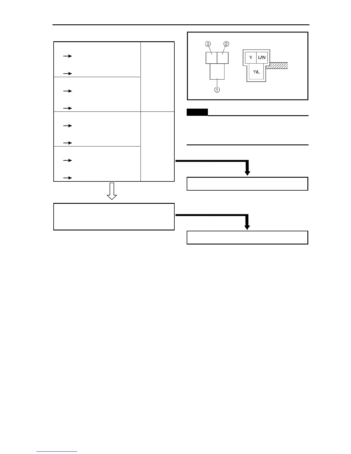
Tester (+) lead
Yellow/Blue terminal ①
Tester(–)lead
Yellow terminal ②
Tester(+) lead
Yellow/Blue terminal ①
Tester (–) lead
Blue/White terminal ③
Continuity
Tester (+)lead
Yellow terminal
②
Tester (–) lead
Yellow/Blue terminal ①
Tester(+) lead
Blue/White terminal ③
Tester(–)lead
Yellow/Blue terminal ①
NO
Continuity
CORRECT
9. Wiring connection
• Check the connections of the entire starting
system. Refer to “CIRCUIT DIAGRAM”.
NOTE:
When you switch the tester’s positive and
negative probes, the readings in the left chart
will be reversed.
INCORRECT
Replace the diode 1.
POOR CONNECTION
Properly connect the starting system.

Table of Contents