System Description - Input Functions
Part No.: 4418309_Rev09 Fusion4 MSC-L
Honeywell Installation & Operation Manual 3 - 43
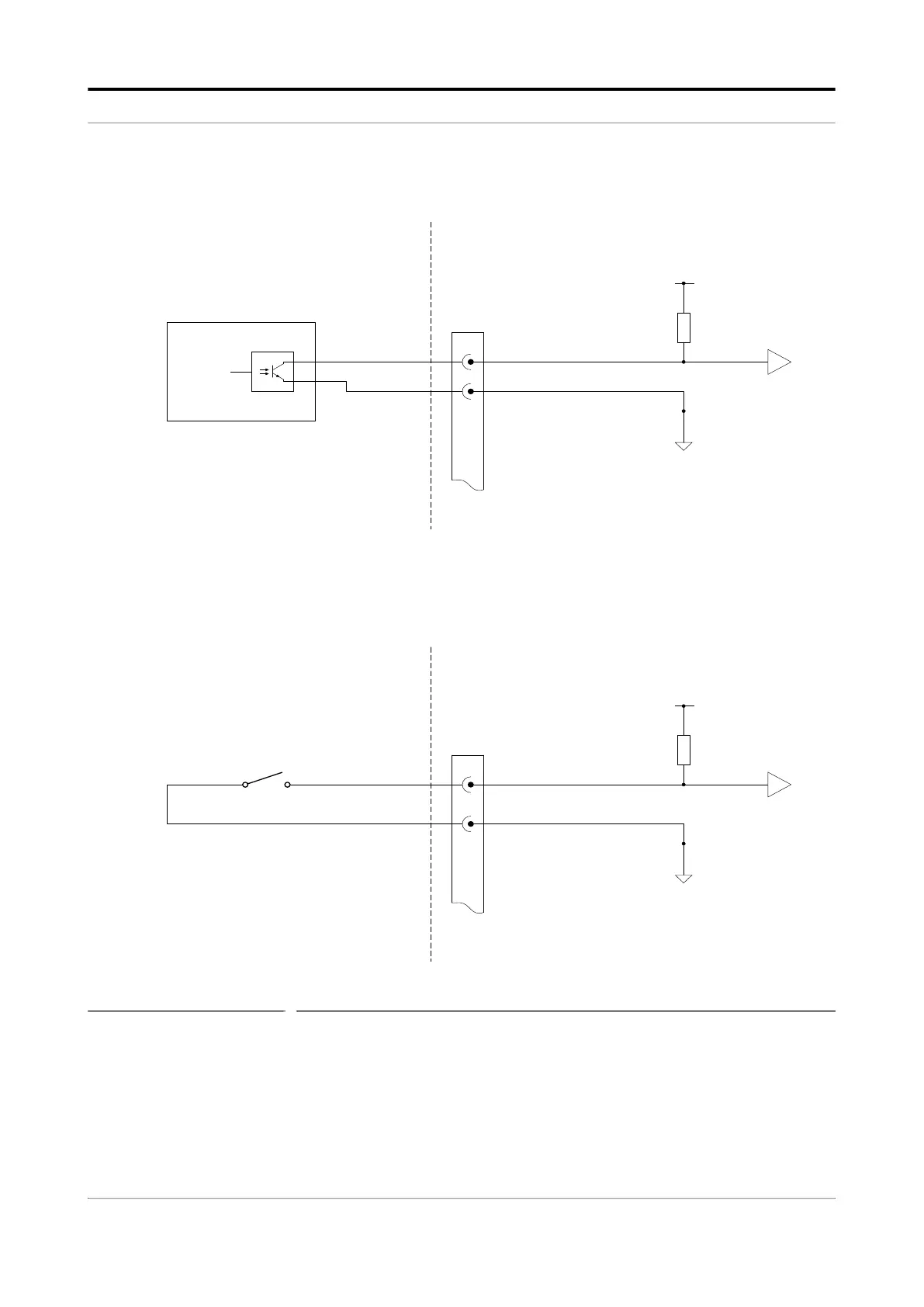
FIGURE 3-26 illustrates the simplified block diagram of the Single Pulse
Input connections.
FIGURE 3-26 Single Pulse Input connections
NOTE: The connector CN135 used in the illustration refers
to the connector on the backplane that connects to
QPI1. This is only an example.
NPN open collector-emitter
(Load computer, PLC, or TAS)
CAN-ARM-MSC
+5V
0V
R
3
2
CN135
PULSE A
COMMON
3
Voltage free contact
+5V
0V
R
CN135
2
or
External equipment
CSM-MRA-NACtnempiuqe lanretxE

 Loading...


