EasyManuals Logo

Honeywell GasLab Q2 User Manual

Honeywell GasLab Q2
266 pages
To Next Page IconTo Next Page
To Previous Page IconTo Previous Page
Page #74 background imageLoading...
Page #74 background image
GASLAB Q2 AFTER DELIVERY AND AT THE PLACE OF USE
Information for general use
Rev. M / 73023639
74
GasLab Q2
Ethernet
Cable type refer to 5.4.2 Cables (power supply / communication) length 100m 328ft.
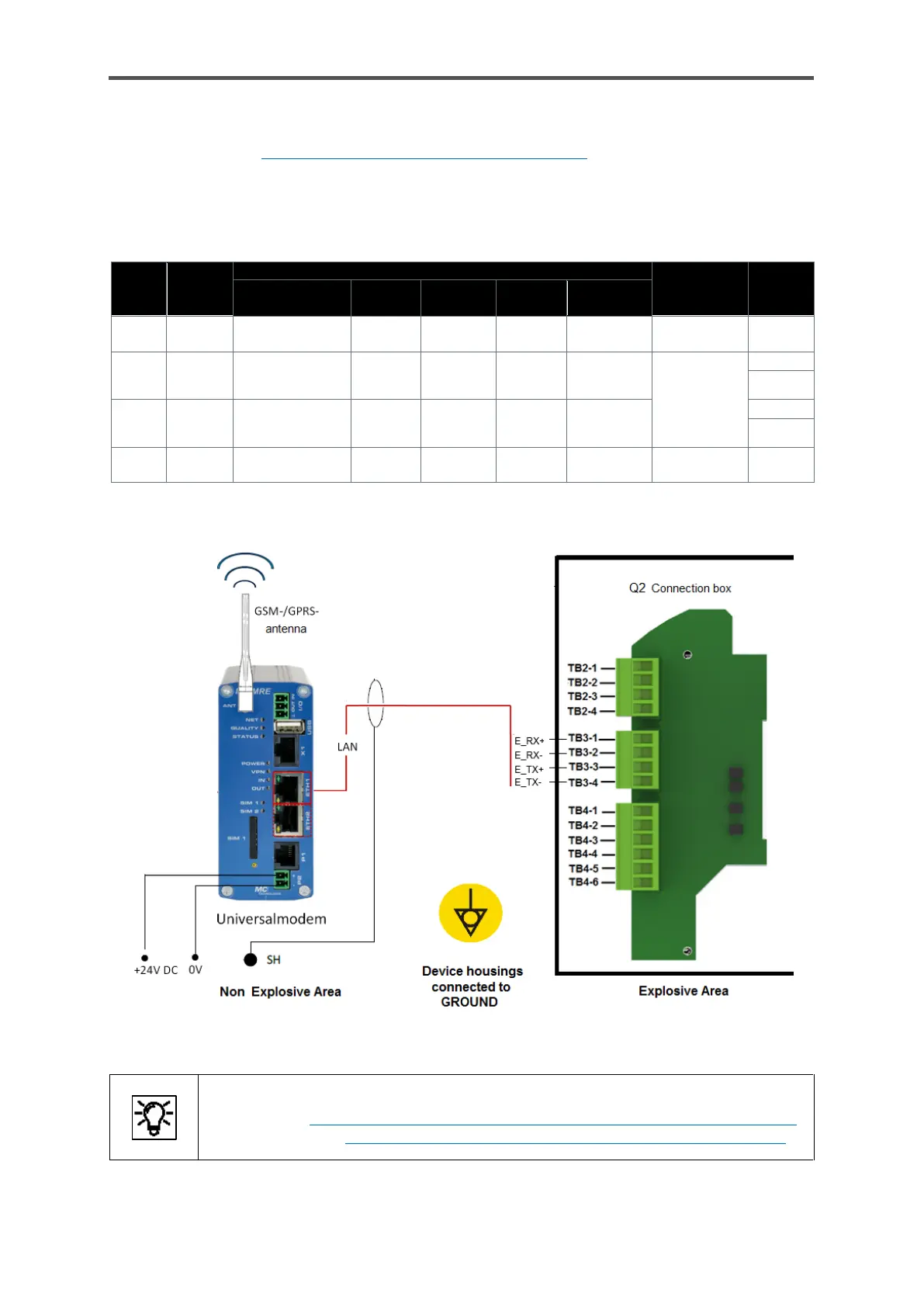
The connection is made using the terminals designated TB3-1 to TB3-4 in the Q2 connection box.
The core colors depend on the standard used, normally EIA/TIA 568B. The twisted pairs must not be
untwisted or regrouped. The polarity of the cores within the core pair is unimportant and the core
pairs can even be swapped.
Core
pair
Plug
(pins)
Color depending on standard
Remark
Terminal
inside
Q2
EIA/TIA 568 B
EIA/TIA
568 A
IEC
REA
DIN 47.100
1
4 / 5
blue + white/blue
blue +
white
white/+
blue
white+
blue
white+
brown
2
3 / 6
white/green
+ green
white +
orange
red+
orange
turquoise
violet
green+
yellow
Only core
pairs 2 and 3
are required
TB3-3
TB3-4
3
1 / 2
white/orange
+ orange
white +
green
black+
grey
white+
orange
grey +
pink
TB3-1
TB3-2
4
7 / 8
white/brown +
brown
white +
brown
yellow+
brown
turquoise+
violet
blue +
red
The following drawing is only designed to illustrate the screening using an example.
Figure 5.7: Sample LAN/Ethernet connection (diagram)
Additional to the wiring, settings must be made before this interface can be used.
On the Q2 7.3.14 System display I/O (basic network settings / Inputs /Outputs)
Or with enSuite 8.4.5 Changing the IP address basic network and I/O settings”.

Table of Contents

Questions and Answers:

Question and Answer IconNeed help?

Do you have a question about the Honeywell GasLab Q2 and is the answer not in the manual?

Honeywell GasLab Q2 Specifications

General IconGeneral
BrandHoneywell
ModelGasLab Q2
CategoryMeasuring Instruments
LanguageEnglish

Related product manuals