Serial interface RS485
Connections include, for example, other measurement devices, devices for final processing and
evaluation, PLC systems, and so on. Cable type refer to 5.4.2.Cables (power supply /
communication).
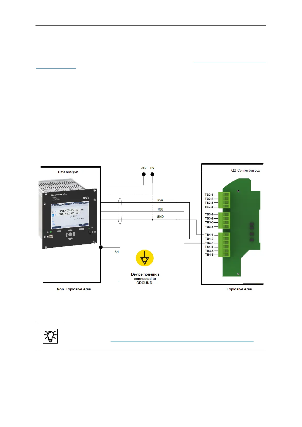
There are 2 interfaces in the connection box (TB4-terminals 1 to 3 for CH1 and TB4-terminals 4 to
6 for CH2, details see figure 5.6). The connection varies depending on the device (see dotted cable
in the following example). The ground (0 V) is either connected directly to the device/system or
connected to GND.
Pull-up / pull-down resistors should be installed at the cable end near the data evaluation unit to
generate the neutral potential. A 470 Ω resistor must be connected between RSA and the positive
supply voltage of the connected data evaluation unit. A further 470 Ω resistor must be connected
between RSB and GND. For cable lengths over 200 m ≙ 656ft, additional bus connection resistors
of 120 Ω each between RSA and RSB at the cable end at the data evaluation unit are recommended.
The following drawing is only designed to illustrate the screening using an example.
Figure 5.8: Example of RS485 connection (diagram)
In addition to the wiring, various enSuite settings are required before this interface
can be used. 8.4.5 Changing the IP address basic network and I/O settings”.
 Loading...