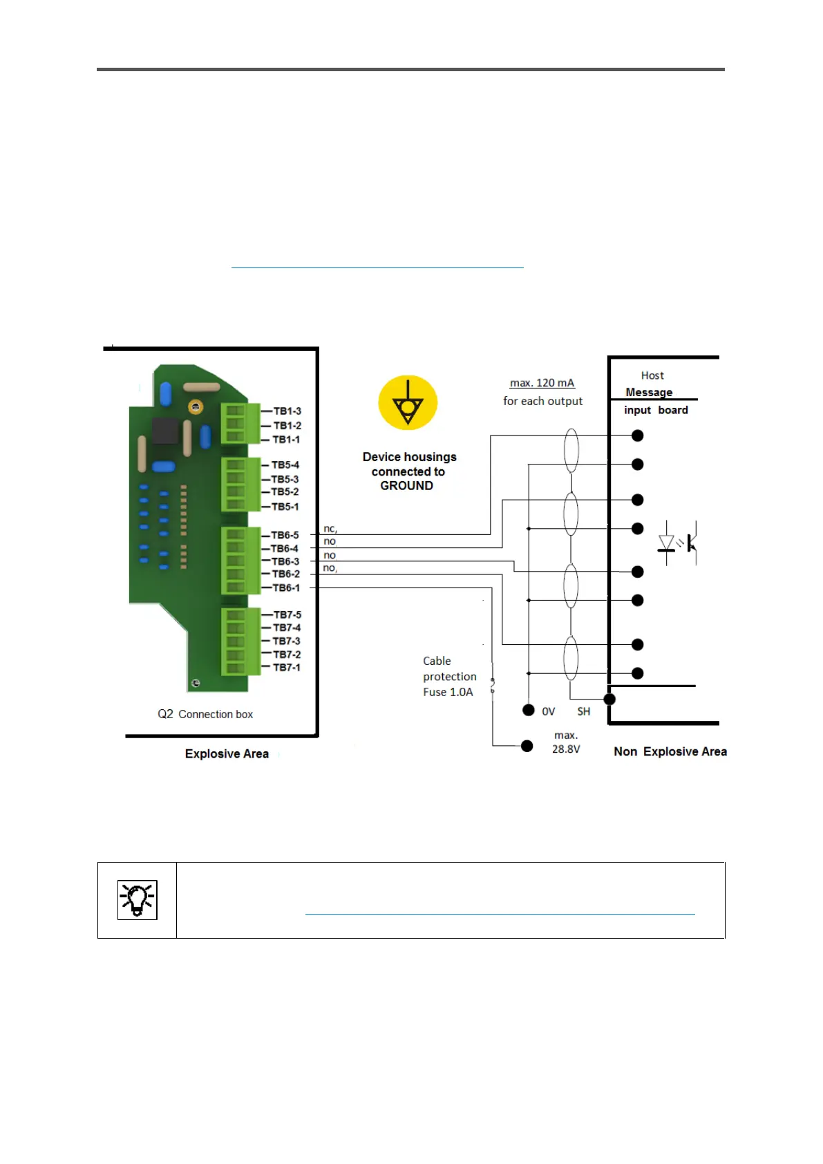
Digital outputs
There are four digital outputs (electrically isolated passive output circuits) in the connection box
(TB6-terminals, details see figure 5.6).
The output at TB6-5 is a breaker (NC, “normally closed”), the other outputs are makers (NO,
“normally open”). The maximum load per channel is 28.8 V DC/120 mA. The maximum pulse rate is
25 Hz.
Cable type refer to 5.4.2 Cables (power supply / communication) the maximum length is 250m ≙
820ft. The figure also shows the appropriate terminals in the connection box. The wiring in the
drawing is only designed to illustrate the screening using an example.
Figure 5.10: Example connection of digital outputs
In addition to the wiring, various enSuite settings are required before this interface
can be used. 8.4.5 Changing the IP address basic network and I/O settings
 Loading...