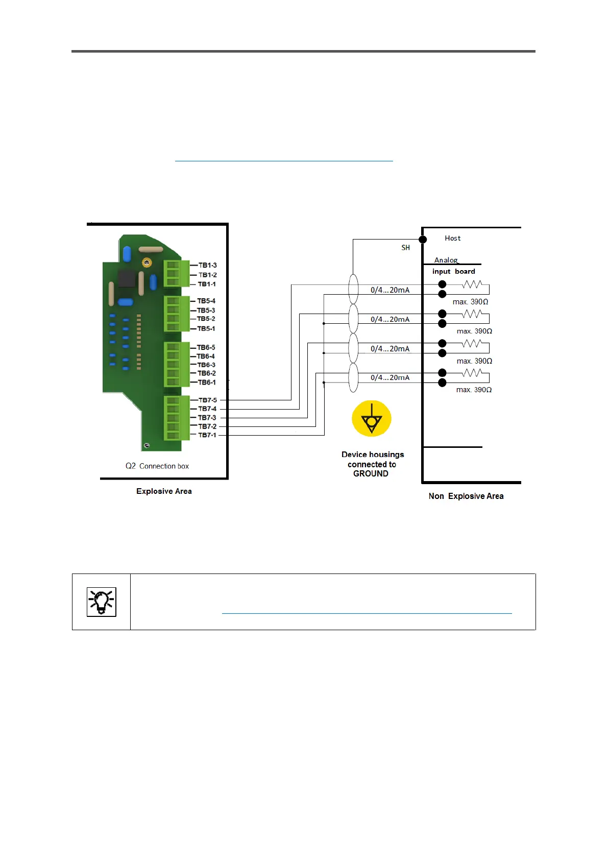
Analog outputs
There are four common electrically isolated active output circuits (“common ground”/short-circuit-
resistant) with 0 or 4 to 20 mA in the connection box (TB7-terminals, details see figure 5.6). The
maximum supply voltage is around 9 V. The maximum load is 390 Ω.
Cable type refer to 5.4.2 Cables (power supply / communication) the maximum cable length is
500m ≙ 1640ft. The figure also shows the appropriate terminals in the connection box. The wiring
in the drawing is only designed to illustrate the screening using an example.
Figure 5.11: Sample connection of digital outputs
In addition to the wiring, various enSuite settings are required before this interface
can be used. 8.4.5 Changing the IP address basic network and I/O settings.
 Loading...