199
Field Descri
tion
Max age(s) Maximum age of a configuration BPDU.
Forward delay(s) Port state transition delay, in seconds.
Hello time(s) Configuration BPDU transmission interval, in seconds.
Max hops Maximum hops of the current MST region.
Return to MSTP configuration task list.
MSTP configuration example
Network requirements
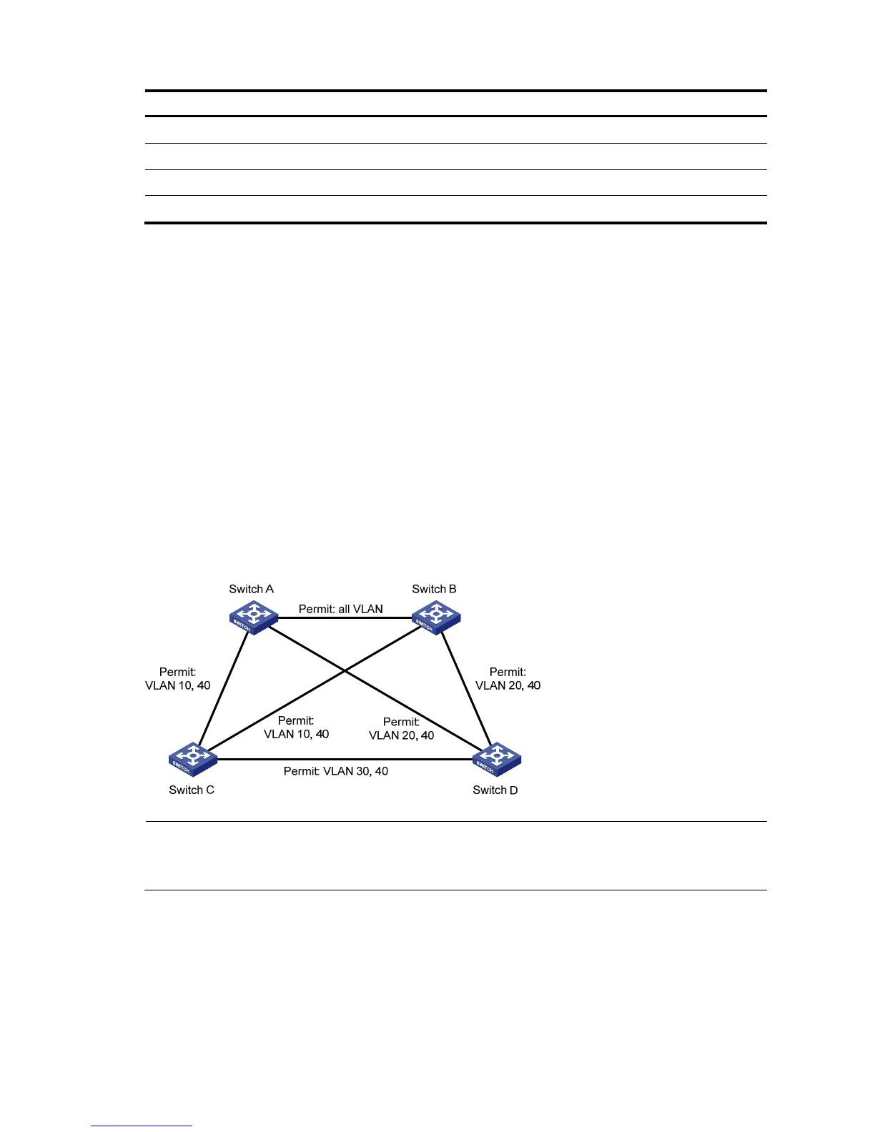
Configure MSTP in the network shown in a to enable packets of different VLANs to be forwarded along
different MSTIs.
All devices on the network are in the same MST region.
Packets of VLAN 10, VLAN 20, VLAN 30, and VLAN 40 are forwarded along MSTI 1, MSTI 2, MSTI
3, and MSTI 0 respectively.
Switch A and Switch B operate at the distribution layer; Switch C and Switch D operate at the access
layer. VLAN 10 and VLAN 20 are terminated on the distribution layer devices, and VLAN 30 is
terminated on the access layer devices, so the root bridges of MSTI 1 and MSTI 2 are Switch A and
Switch B respectively, while the root bridge of MSTI 3 is Switch C.
a. Network diagram for MSTP configuration
NOTE:
“Permit” next to a link in the figure is followed by the VLANs the packets of which are permitted to pass this
link.
Configuration procedure
Table 48 Configure Switch A.
# Configure an MST region.
Select Network MSTP from the navigation tree to enter the page shown in b.