269
Item Descri
tion
Interface
Select the output interface.
You can select any available interface, for example, a virtual interface, of the
device. If you select NULL 0, the destination IP address is unreachable.
Static route configuration example
Network requirements
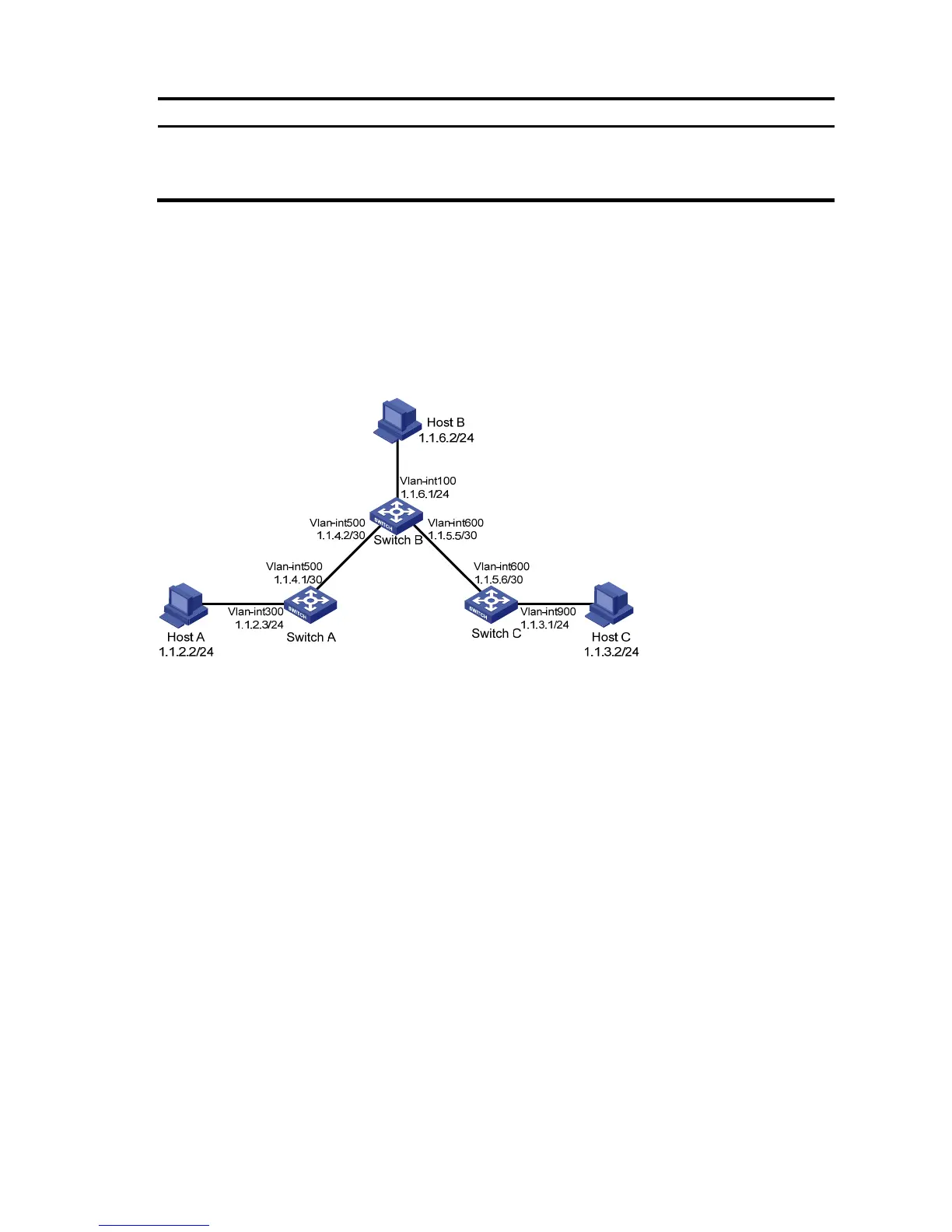
The IP addresses of devices are shown in a. Configure IPv4 static routes on Switch A, Switch B, and Switch
C so that any two hosts can communicate with each other.
a. Network diagram for IPv4 static route configuration
Configuration outlines
Table 68 On Switch A, configure a default route with Switch B as the next hop.
Table 69 On Switch B, configure one static route with Switch A as the next hop and the other with Switch
C as the next hop.
Table 70 On Switch C, configure a default route with Switch B as the next hop.
Configuration procedure
Table 71 Configure the IP addresses of the interfaces (omitted)
Table 72 Configure IPv4 static routes
# Configure a default route to Switch B on Switch A.
Select Network IPv4 Routing from the navigation tree of Switch A, and then click the Create tab to
enter the page shown in b.
Type 0.0.0.0 for Destination IP Address.
Select 0 (0.0.0.0) from the Mask drop-down list.
Type 1.1.4.2 for Next Hop.
Click Apply.