37
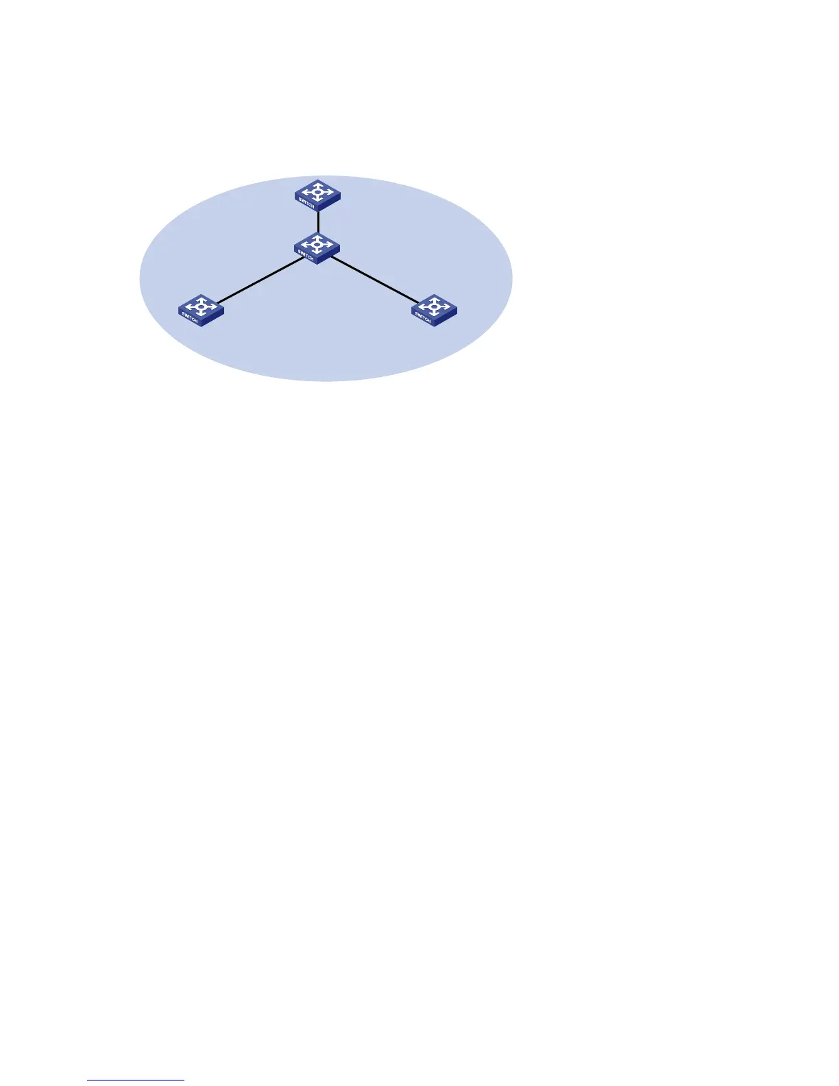
Create a stack, where Switch A is the master switch, Switch B, Switch C, and Switch D are stack
members. An administrator can log in to Switch B, Switch C and Switch D through Switch A to perform
remote configurations.
a. Network diagram for stack management
Eth1/0/1
Eth1/0/3
Switch B
Eth1/0/1Eth1/0/1
Switch C Switch D
Stack
Eth1/0/1
Eth1/0/2
Switch A
(Master switch)
Configuration procedure
Table 15 Configure the master switch
# Configure global parameters for the stack on Switch A.
Select IRF from the navigation tree of Switch A to enter the page of the Setup tab.