Table 6. SRC Break Down Table (continued)
SRC Word
Control Panel
Function
Panel Function
Characters Format Description
7 13 9-16 BBBB Ccbb Bus, Card, board Direct Select Address
(DSA). See “Determining a Part Position
and Item From the Direct Select Address”.
If BBBB is greater than or equal to 0100,
then the BBBB value is the HSL loop
number.
8 13 17-24 TTTT MMMM Type and Model of failing item (if
non-zero)
9 13 25-32 uuuu uuuu Unit Address (if non-zero)
Determining a Part Position and Item From the Direct Select Address:
1. Break down the DSA into the bus number, the multi-adapter bridge number
and the multi-adapter bridge function number as shown in the Table 7.
2. Use the System Configuration List or Hardware Service Manager (HSM) to
determine if the bus is located in the system unit or an I/O tower.
3. Refer to the “Card Position Tables” on page 282. Search for the bus number, the
multi-adapter bridge number and the multi-adapter bridge function number in
the Card Position Table that matches the system unit or the I/O tower type
where the bus is located.
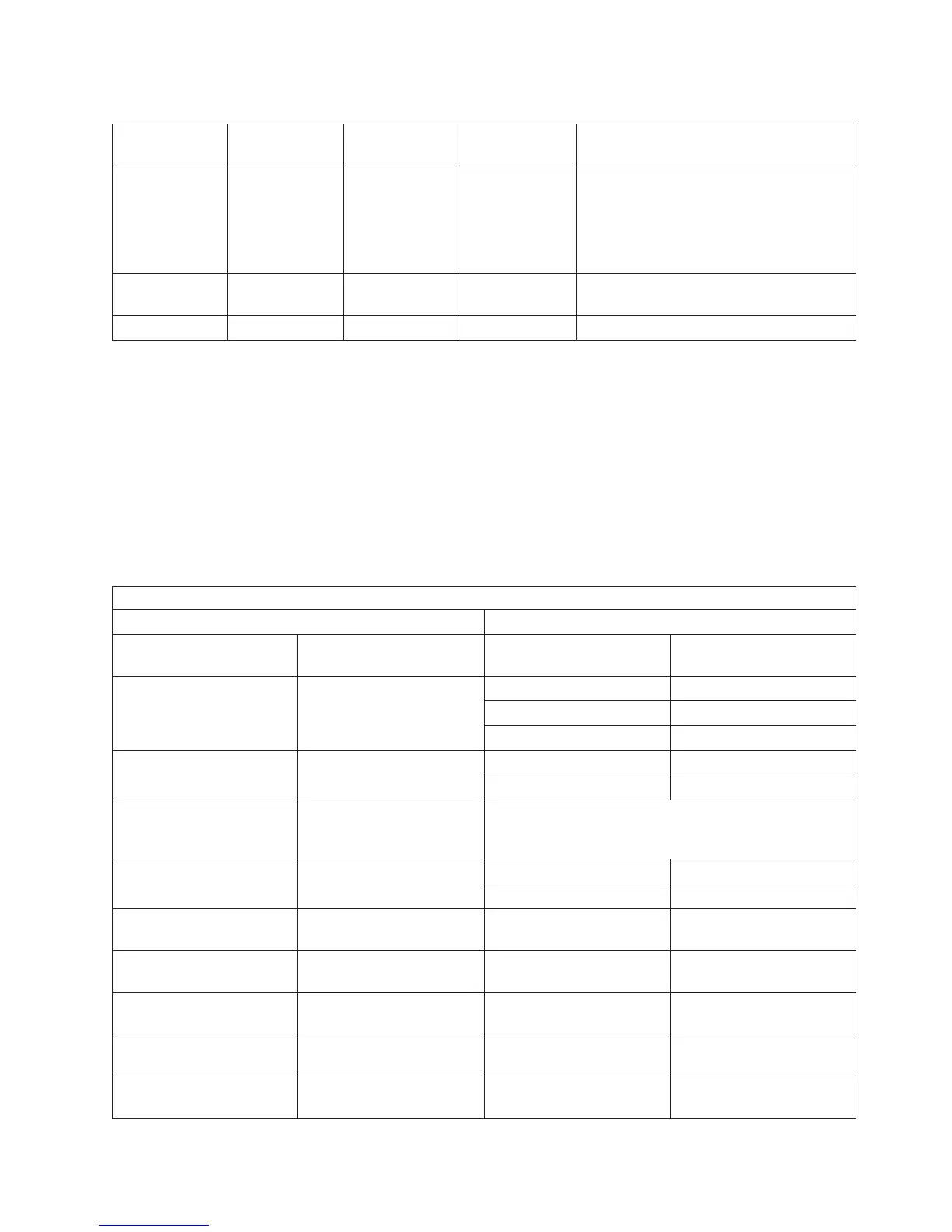
Table 7. DSA Break Down Table
The DSA Format is: BBBB Ccbb (bb is not used)
BBBB = Bus Number Cc = Card identifier
Bus Number The bus type is: C = The Multi-adapter
Bridge Number
c = The Multi-adapter
Bridge Function Number
0001 PCI 1 0 through 7
2 0 through 7
70
0002 through 0003 PCI 1 0 through 7
2 0 through 7
0004 through 0017 SPD Logical Card Number (See the Bus Overview section in
the Migrated Expansion Tower Problem Analysis, Repair and
Parts.
0018 through 00FF PCI 1 0 through 7
2 0 through 7
0100 HSL loop number 256
(decimal)
N/A N/A
0101 HSL loop number 257
(decimal)
N/A N/A
0102 HSL loop number 258
(decimal)
N/A N/A
0103 HSL loop number 259
(decimal)
N/A N/A
0104 HSL loop number 260
(decimal)
N/A N/A
Bus, High-Speed Link (HSL) PIPs
Chapter 3. Problem Isolation Procedures (PIPs), Failing Items, and Symbolic FRU Isolation 281