Note: If the Failing Item is a System Sub-Card, for example, a DIMM on a
Memory Riser Card, the Location will have a sub-card letter, for
example, M02-A, where M02 is the card slot and A is the sub-card
letter.
This ends the procedure.
6. The ″Type number″ from the FRU information is zero:
v Use the Location information from the ″Reference Code Table″ to get the
FRU Name and the physical mapping information from the “Locations and
Addresses” on page 705.
7. If needed, use control panel function 20 to determine the Processor Feature
Code.
8. Use the FRU name and, if needed, the Processor Feature Code, to reference
the appropriate table below to determine the type number for the failing item.
Then, determine the Part Number from the “Type, Model, and Part Number
list” on page 885.
9. Go to step 4 on page 518 of this procedure.
10. Is the system a model 840 or SB3?
Yes No
↓ For Models 830/SB2:
Attention: When replacing the system unit backplane (MB1) on a
model 830/SB2 it is ″required″ that the processor cards be replaced
also (For additional information, refer to the “Model 830/SB2 –
Processor Feature Codes and CCINs” on page 890).
Then, continue with step 5 on page 518 of this procedure.
11. Replace the System Unit Backplane in location MB1. See the Table 42 on
page 720 for location MB1 and FRU ″System Unit Backplane″ to determine the
CCIN and Removal and Installation procedure.
This ends the procedure.
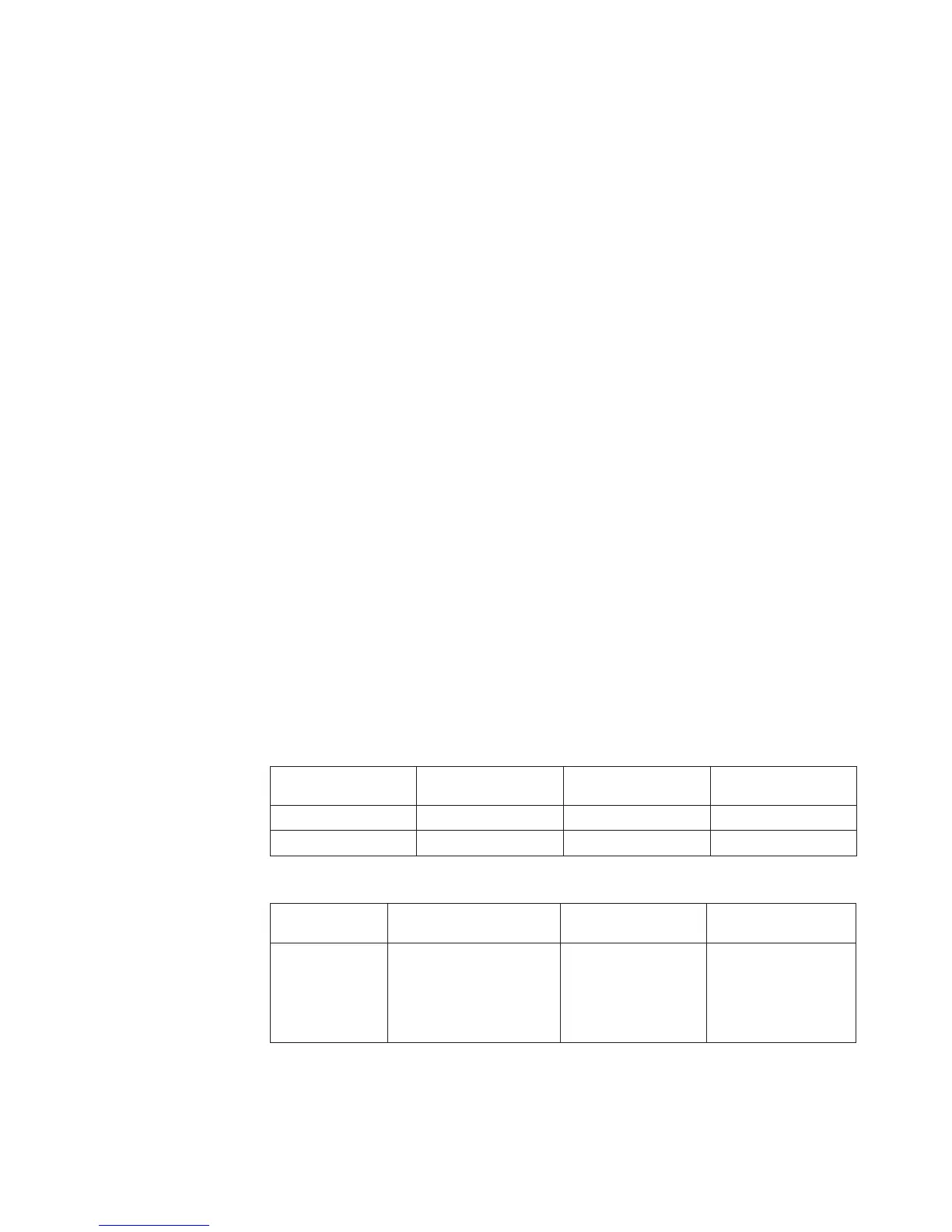
Table 20. Backplane Type Numbers
Model Processor Feature
Code
Backplane Type Location
830, SB2 All 281A MB1
840, SB3 All 282B MB1
Table 21. Processor and Clock Card Type Numbers
Model Processor Feature Code Processor or Clock
Card Type
Location
830 23C1, 23C2, 23C3, 23C4,
23C5
Processor Card
v 245C
Clock Card
v 25AB
Processor Card
v M03 or M04
Clock Card
v M06A
Symbolic FRUs
Chapter 3. Problem Isolation Procedures (PIPs), Failing Items, and Symbolic FRU Isolation 519