intel.
8XC51FXHARDWAREDESCRIPTION
Table 6. TCON: Timer/Counter Control Register
I
TCON Address = 88H
ResetValue = 0000 OOOOB
BitAddressable
I
TF1
TR1
TFO
TRO IE1 IT1
IEO
ITO
Bit 7 6 5
4
3 2 1
0
Symbol
Function
TF1
Timer1overflowFlag.SetbyhardwareonTimer/Counteroverflow.Clearedby
hardwerewhenproceseorvectorsto interruptroutine.
TR1
Timer1Runcontrolbit.Set/clearedbysoftwareto turnTimer/Counter1on/off.
TFO
TimerOoverflowFlag.SetbyhardwareonTimer/CounterOoverflow.Clearedby
hardwarewhenprocessorvectorstointerruptroutine.
TRO
TimerORuncontrolbit.Set/clearedbysoftwareto turnTimer/CounterOon/off.
IE1
Interrupt1flag.Setbyhardwarewhenexternalinterrupt1edgeisdetected
(transmittedor level-activated).Clearedwheninterruptprocessedonlyif transition-
activated.
IT1
Interrupt1Typecontrolbit.Set/clearedbysoftwareto specifyfallingedge/lowlevel
triggeredexternalinterrupt1.
IEO
InterruptOflag.SetbyhardwarewhenexternalinterruptOedgeisdetected
(transmittedorlevel-activated).Clearedwheninterruptprocessedonlyif transition-
activated.
ITO
InterruptOTypecontrolbit.Set/clearedbysoftwareto specifyfallingedge/lowlevel
triggeredexternalinterruptO.
x=Oor 1
270S53-S4
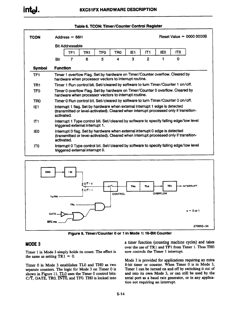
Figure 9. Timer/counter Oor 1 in Mode 1: 16-Bit Counter
MODE3
a timerfunction(countingmachinecycles)andtakes
over the use of TRl and TFl from Timer 1.Thus THO
Timer 1 in Mode 3 simply holds its count. The effect is now controls the Timer 1 interrupt.
the same as setting TR1 = O.
Mode 3 is provided for applications requiringan extra
Timer O in Mode 3 establishes TLOand THO as two
8-bit timer or counter. When Timer Ois in Mode 3,
separatecounters. Tlse logic for Mode 3 on Timer Ois
Timer 1can be turned on and off by switching it out of
she–m in Figure 11. TLOuseathe Timer Ocontrol bits:
and into its own Mode 3, or can still be used by the
C/T, GATE, TRO,INTO, and TFO.THOis locked into
serialport as a baud rate generator,or in any applica-
tion not requiring an interrupt.
5-14