i~e
87C51GBHARDWARE DESCRIPTION
flowsetsthe TF2bit and causeaOFFFFHto bereload-
ed into the timer registers.
The EXF2bit toggleawheneverTimer 2 overflowsor
underflows.Thisbit can be usedas a 17thbit ofresolu-
tion if desired.In this operatingmode,EXF2doesnot
generatean interrupt.
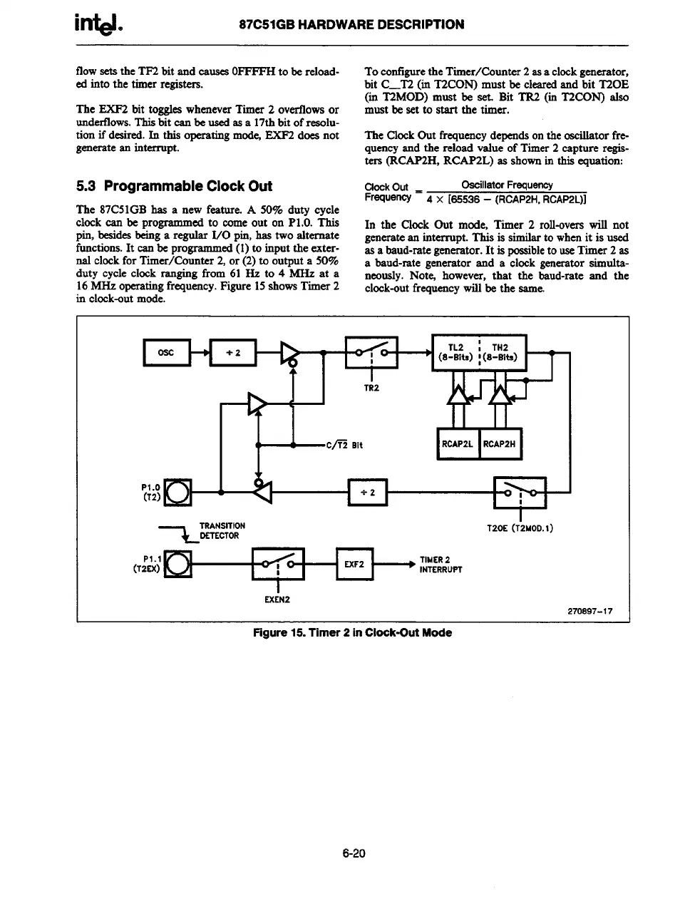
5.3 Programmable Clock Out
The 87C51GBhas a new feature. A 50% duty cvcle
Toconfigurethe Timer/Counter 2as a clockgenerator,
bit C—T2(in T2CON)must be clearedand bit T20E
$us~&M~~jof~ ~esetet~it TR2 (in T2CON) ako
The ClockOut frequencydependsonthe osdator fre-
quencyand the reload value of Timer2 capture regis-
ters (RCAP2H,RCAP2L)m shownin this equation:
ClockOut.
oscillatorFrequency
Frequency 4 x [65536– (Rc/4p2H, Rr&4p2L)]
clock can be programmedto comeout on P1.b. h
In the Clock Out mode, Timer 2 roll-overswill not
pin, besidesbeinga regular 1/0 pin,has two alternate
functions.It canbe programmed(1)to inputthe exter-
generatean interrupt. This is similarto whenit is used
nal clockfor Timer/Counter 2,or (2)to output a 50%
as a baud-rategenerator.It is possibleto useTimer 2 as
duty cycle clock ranging from 61 Hz to 4 MHz at a
a baud-rate generator and a clock generatorsimulta-
16MHz operatingfrequency.Figure15showsTimer 2
neously.Note+however, that the baud-rate and the
clock-outfrequencywillbe the same.
in clock-outmode.
-T--r+J
11
WI
1-
c“Bit EIEl I
P1.o
!
1>1
I
(12)
w
I
+2
I
1
1
I
~T&N%:N
T20E (T2M0D. t)
P1.1 [-l
(122)0
t
I
I
EX~N2
270897-17
Figure15.Timer2 inClook-OutMode
6-2o