87C51GB HARDWARE DESCRIPTION
thrOU@ CMP7correspondto analogiStPUtS Othrough
7. CMPnis set to a 1if theanaloginput is greaterthan
COMPREF.CMPnis clearedif the analoginputis leas
than or equalto COMPREF.
ACON is the A/D control register and contains the
A/D Interrupt Flag (AIF), A/D ConversionEnable
(ACE),A/D ChannelSelect(ACSOand ACS1),A/D
Input Mode(AIM), and A/D TriggerMode(ATM).
6.2 A/D Comparison Mode
TheA/D Comparisonmodeis alwaysactivewhilethe
A/D converteris enabled.The Comparisonmode is
usedto compareeachanaloginput against an external
referencevoltageappliedto COMPREF.Wheneverthe
A/D converteristriggered,eachbit in ACMPisupdat-
ed as each analog conversionis completed, starting
with channelOup to channel 7 regardlessof whether
Selector Scanmodeis invoked.The comparisonmode
can providea quicker“greater-thanor leas-than”deci.
sionthan canbeperformedwithsoftwareand it ismore
codeeffkient.It canalsobe usedto cmsvertthe analog
inputsinto digitalinputs with a variable threshold.If
the comparisonmodeis not w@ COMPREFshould
be tied to Vcc or VW.
6.3 A/D Trigger Mode
Theanalogconvertercanbetriggeredeither internally
or externally.To enable internal trigger mode, ATM
shouldbe ck.ared.
Whenin internaltriggermode,A/D conversionsbegin
in the machinecycle which followsthe setting of the
ACEbit. The lowestcharmeI(see“AA) Input Modes”
below)isconvertedtlraLfollowedbyall the otherchan-
nels in sequence.The AIF fiag is set upon completion
ofthe channel7 conversion.AIF willtlag an interrupt
if the A/D interrupt is enabled.once a conversioncy-
cle is complete4 a newcyclebe- starting with the
loweatchannel. If the user wisheseach channel to be
convertedonly once, the ACE bit should be cleared.
ClearingACE stops all A/D conversionactivity.If a
newA/D cyclebegin$the result of the previouscon-
versionwillbe overwritten.
In externalmode,the A/D conversionsbeginwhena
fallingedgeisdetectedat theTRIGIN pin.Thereis no
edgedetector on the TRIGIN pin; is it sampledonce
everymachinecycle.
A negativeedgeis recognizedwhenTRIGIN is highin
onemachinecycleand lowin the next.For this reason,
TRIGIN shouldbe held highfor at least
onemachine
cycleand lowfor onemachinecycle. Once the fklling
edgeisdetected,the A/D mnversiottsbeginon the next
machinecycleandcompletewhenchannel7is convert-
ed. After channel 7 is czxsvert@ AIF is set and the
conversionshalt until another trigger is detectedwhile
ACE= 1.Externaltriggersare ignoredwhilea conver-
sioncycleis in progreas.
6.4 A/D Input Modes
The 8XC51GBhas two input modes:Scan mode and
Select mode. Clearing AIM places the 8XC51GBin
Scanmode.In Scanmodethe arsrdogconversionsoccur
in the sequenceACHO,ACH1, ACH2,ACH3,ACH4,
ACH5, ACH6, and ACH7. The reault of each analog
conversionis placedin the correspondinganalogremdt
register: ADO,ADl, AD2, AD3, AD4, AD5, AD6,
and AD7.
Setting AIM activatesselect mode.In Selectmode one
of the lower4 analoginputs (ACHO-ACH3)is con-
verted four times. After the first four conversionsare
complete the cycle continues with ACH4 through
ACH7. The results of the first four conversionare
placedin the lowerfour result registers(ADOthrough
AD3). The rest of the conversionsare placed in their
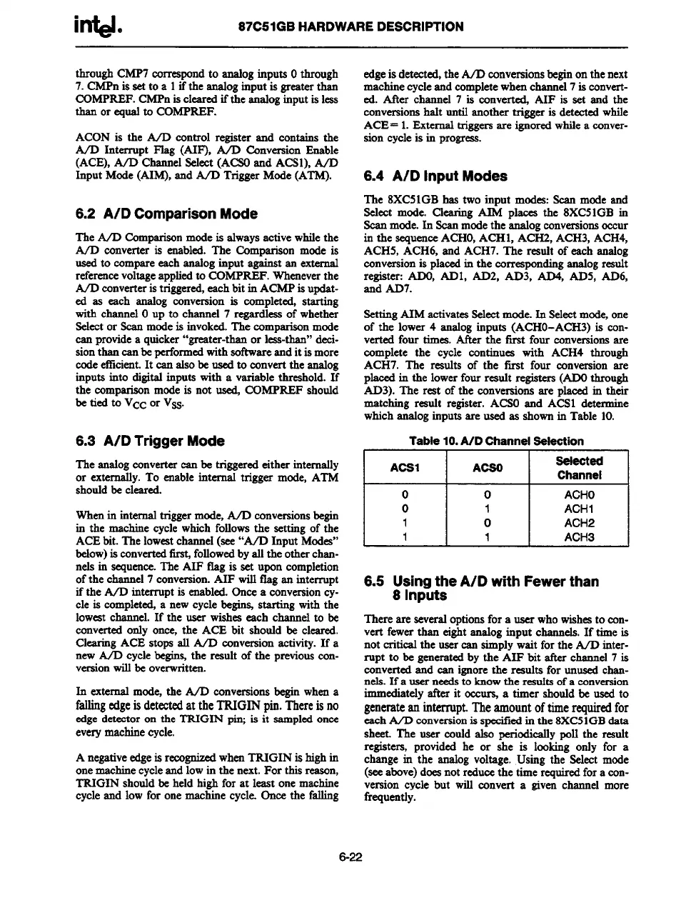
matching result register. ACSOand ACS1 determine
whichanaloginputsare used as ahownin Table 10.
Table10.A/D Channelselection
ACS1
ACSO
Seiected
Channel
o 0 ACHO
o
1
ACH1
1 0 ACH2
1 1 ACH3
6.5 Using the A/D withFewer than
8 Inputs
There are severaloptionsfor a user whowishesto con-
vert fewerthan eightanaloginput channels.If time is
not critical the usercan simplywait forthe A/D inter-
rupt to be generatedby the AIF bit after channel7 is
convertedand can ignorethe results for unusedchan-
nels.Ifa userneedsto knowthe resutts
of a conversion
immediatelyafter it occw a tinter shouldbe usedto
generateaninterrupt.Theamountoftimerequiredfor
eachA/D conversionis specitiedin the 8XC51GBdata
sheet. The user could also periodicallypoll the result
rebte~: provided he or she is lcoking only for a
change m the analogvoltage. Using the Select mode
(seeabove)doesnotreducethe timerequiredfor a con-
version cycle but will convert a given channel more
frequently.
6-22