intd.
87C51GB HARDWARE DESCRIPTION
4. There has beenone additionalbit added to CICON
to ~OWboth PCASto be enabledsirmdtrmeou.dy.
Thebit is calledCRE and occupiesbit position5of
CICN. Its bit addressis OEDH.When CRE is set,
both CR and CR1 must be set to enablePCA1.
Each PCA mnsiats of a id-bit tisner/counter and five
16-bitcompare/capture modulesas shown in Figure
17.The PCA timer/counter servesas a
commontime
base for the five modulesand is the only timer which
can service the PCA. Its clock input can be pro-
grammedto count any one of the followingsignals:
Oscillatorfrequency/ 12
oscillator fkequency/ 4
TimerOoverflow
Externalinput on ECI (P1.2).
The comparehpture modulescan be programmedin
any oneofthe followingmodes:
risingand/or fallingedgecapture
softwaretimer
highSpeedoutput
pulsewidth modulator.
Module 4 can also be programm
ed as a watchdog
timer.
Whenthe compare/capture modulesare programmed
in the capturemod$ softwaretimer, or highspeedout-
put mode,an interrupt can be generatedwhenexerthe
moduleexecutesits function.All fivemodulesplusthe
PCAtimer overflowshare one PCA interrupt vector.
ThePCAtimer/counter and compare/capturemcdules
sharePort 1pinsforexternal1/0. Thesepinsare listed
below.If the port pin is not used for the PCAj it can
stillbe usedfor st&dard 1/0.
PCAComponent External1/0 Pin
16-bitCounter
16-bitModuleO
16-bitModule1
16-bitModule2
16-bitModule3
16-bitModule4
P1.2/ ECI
P1.3/ CEXO
P1.4I CEX1
P1.5/ CEX2
P1.6/ CEX3
P1.7/ CEX4
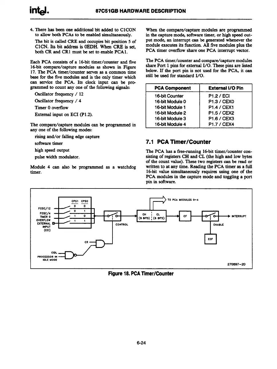
7.1
PCATimer/Counter
The PCAhas a free-running16-bittimer/counter con-
sistingof registersCH and CL (the highand lowbytes
of the countvalue).Thesetwo registerscan be read or
writtento at any time.Readingthe PCA timer as a full
16-bitvalue simultaneouslyrequires using one of the
PCA mcduleain the capture modeand togglinga port
pin in sotlware.
FOsc/12
Fosc/4
TIMER0
OVERFLOW
EXTERMAL
INPUT
(ECI)
& ~-w ~‘~ “7’-
CPSICPSO
TO PCA MODULSS0-4
——
00
01
10
(s:Hm) { (8c&s)
CF
1 1
CONTROL
ENASLE
/
CR
CIDL
PROCSSSORIN
IDLE UOOE
INTERRuPT
Figure18.PCATimer/Counter
6-24