87C51GB HARDWARE DESCRIPTION
Theclockinputcan be selectedfromthe followingfour
modes:
Oscillatorfraquancy/ 12:
ThePCA timer increments once per machine cycle.
With a 16 MIiz crystal, the timer increments evety
750m.
Oscillatorfrequency/ 4:
The PCA timer increments three times per machine
cycle. With a 16 MHz crystal, the timer increments
every250ns.
TimerOoverflows:
ThePCA timer increments wheneverTimer O over-
flows. This mode allows a programmableinput fre-
quencyto the PCA.
Externalinput:
ThePCA timer incrementswhena l-to-Otransition is
detected on the ECI pin (P1.2).The maximuminput
frequencyin this modeis oscillatorfrequency/ 8.
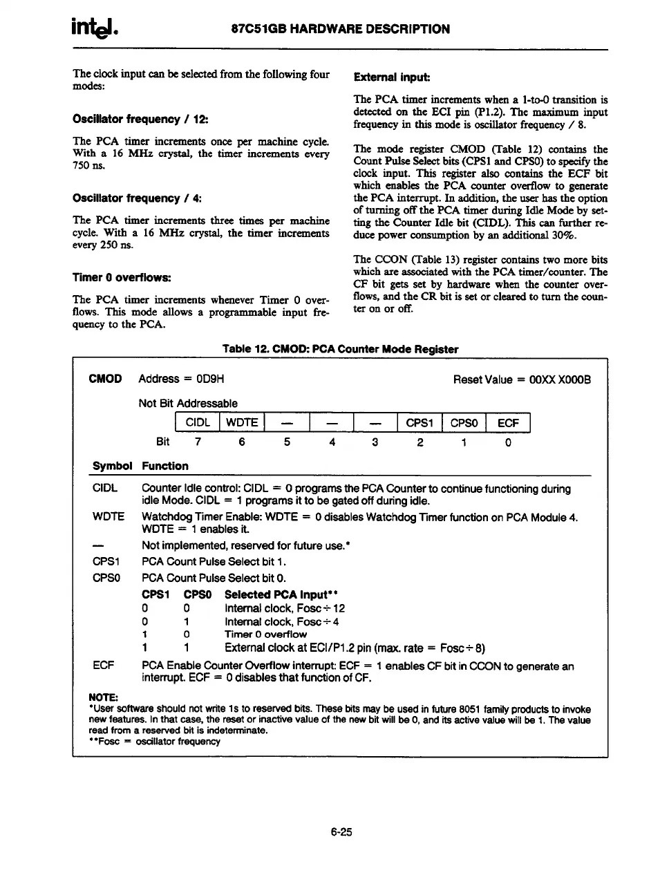
The mode register CMOD (Table 12) contains the
CountPulseSelectbits(CPS1and CPSO)to specifythe
clock input. This register also contains the ECF bit
whichenables the PCA counter overflowto generate
the PCA interrupt. In addition,the userhas the option
ofturning off the PCA timer duringIdle Modeby set-
tingthe CounterIdle bit (CIDL). This can further re-
ducepowerconsumptionby an additional30%.
The CCON(Table 13)registercontainstwo more bits
whichare
associatedwiththe PCAtimer/munter. The
CF bit gets set by hardware when the counter over-
flows,and the CRbit isset or clearedto turn the coun-
teron or off.
Table12.CMOD:PCACounterModeRegister
CMOD Address= OD9H
ResetValue= OOXXXOOOB
NotBitAddressable
CIDL
WDTE —l—
—
CPS1
CPSO
ECF
1
Bit 7 6 5
4
3
2
1
0
symbol Funotion
CIDL Canter Idlecontrol:CIDL= OprogramsthePCACountertocontinuefunctioningduring
idleMode.CIDL= 1programsittobegatedoffduringidle.
WDTE WatchdogTimerEnable:WDTE= OdiaablesWatchdogTimerfunctiononPCAModule4.
WDTE= 1enablesit.
—
Notimplemented,reservedforfutureuse.*
CPS1
PCACountPulseSelectbit1.
CPSO
PCACountPulseSaIectbitO.
CPS1 CPSO SelectedPCAInput**
o 0
Internal clock, Foac+ 12
0
1
Internalclock,FOSC+4
1 0
Timer Ooverflow
1 1 External ciookat EC1/Pl.2 pin (max. rate = Fosc+8)
ECF
PCA Enable Counter Overflow interrupt: ECF = 1 enables CF bit in CCON to generste an
interrupt. ECF = Odisables that funotion of CF.
NOTE:
“Usarsoftwareshould
notwriteIs to reservedbits.These bits maybe used in future 8051familyproductstoinvoke
newfeatures.
In that case, the resetor inactivevalue of the newbitwillbe O,and itsactivevaluewill be 1. The value
read froma reservedbitis indeterminate.
..F~ = ~llator frSIJUenCY
6-25