irrl&
87C51GB HARDWARE DESCRIPTION
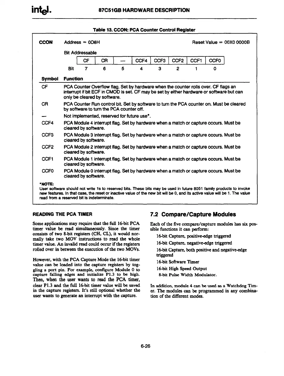
Table13.CCON:PCACounterControlR~ieter
CCON
Address= OD6H
ResetValue= OOXO00006
BitAddressable
! W ! CR I – I CCF4 ] CCF3I CCF2 I CCFI I CCFOI
Bit 7 6 5 4 3 2
1 0
Svmbol Function
CF
PCACounterOverflowflag.Setbyhardwarewhenthecounter
rolls over. CF flags an
interrupt if bit ECF in
CMODis set.CFmaybesetbyeitherhardwareorsoftwarebutcan
onlybeclearedbysoftware.
CR
PCACounterRuncontrolbit.SetbysoftwaretoturnthePCAcounteron.Mustbecleared
byeoflwaretoturnthePCAcounteroff.
Notimplemented,reservedforfutureuse*.
CCF4
PCAModule4 interruptflag.Setbyhardwerewhenamatchorcaptureoccurs.Mustbe
clearedbysoftware.
CCF3
PCAModule3 interruptflag.Setbyhardwarewhenamatchorcaptureoccurs.Mustbe
clearedbysoftware.
CCF2
PCAModule2interruptflag.Setbyhardwarewhena matchorcaptureoccurs.Mustbe
clearedbysoftware.
CCF1
PCAModule1interruptflag.Setbyherdwarewhenamatchorcaptureoccurs.Mustbe
clearedbysoftware.
CCFO
PCAModuleOinterruptflag.Setbyhardwarewhenamatchorcaptureoccurs.Mustbe
clearedbysoftware.
●NOTE:
Useraoftwsreshouldnotwriteletoreservedbite.Thesebitsmeybeusedinfuture8051familyproductstoinvoke
newfeeturee.Inthatease,theresetorinsotiveveluaofthenewbitwillbaO,enditsactivevaluewillbe 1.Thevalue
readfroma resewedbitisindeterminate.
READINGTHEPCATIMER
7.2 Compare/Capture Modules
Someapplicationsmayrequirethat the full Id-bitPCA
timer value be read simultaneously.Since the timer
consistsof two 8-bitregisters(CH, CL), it wouldnor-
mally take two MOV instructionsto read the whole
timervalue.An invalidread could
occurifthe registers
rolledoverin betweenthe executionofthe twoMOVS.
However,withthe PCA CaptureModethe M-bittimer
valuecan be loadedinto the capture registersby tog-
glinga port pin. For example,cofigure ModuleOto
cspture falling edges end initialize P1.3 to be high.
Then, when the user wants to
readthe P(2Atimer,
clearPL3andthefullI&bittimervaluewillbesaved
in the captureregisters.It’sstilloptionalwhetherthe
userwantsto generateeninterruptwiththecapture.
Eachofthe fivecompere/capture meduks has sixpos-
siblefunctionsit can perform:
16-bitCapturq positive-edgetriggered
id-bit Capture,negative-edgetriggered
id-bitCapture,bothpositiveand negative-edge
triggered
16-bitsoftwareTimer
16-bitHighSpeedOutput
8-bitPulseWidth ModuIetor.
In eddition,module4 can be usedes a WatchdogTim-
er. The modulescan be programmedin any combina-
tion of the differentmodea.
6-26