in~.
87C51GB HARDWARE DESCRIPTION
Thebaudrate generatormodeis similarto the auto-re-
loadmcde,in that a rolloverin TH2causesthe Timer 2
registerstobereloadedwiththe Id-bitvsduein registers
RCAP2Hand RCAP2L,whichare presetby software.
The baud rates in Modes 1 and 3 are det
ermined by
Timer2’soverflowrate as follows:
ModesI and 3 = ~mer 2 ov~~ Rate
BaudRates
16
Timer2canbecont@redfor either “timer” or “coun-
ter” operation.In mostapplicati~ it is con@ured for
“timer” operation(C—T2 = O).The “Timer” opere-
tion is differentfor Timer 2 whenit’sbeingused as a
baudrats generator.Normally,es a timer,it increments
everymachinecycle(1/12 the osciUatorfrequency).As
a baud rate generator, howwer, it increments every
state time(1/2the oscillatorfrequency).The baud rate
formulais givenbelow:
Mcdaa1
and 3.
OscillatorFrsqueney
BaudRate
32 x [65536 - (RCAP2H,RCAP2L)]
where (RCAP2H, RCAP2L) is the content of
RCAP2Hand RCAP2Ltaken as a M-bitunsignedin-
teger.
Timer2as a baudrate generatoris validonlyif RCLK
and/or TCLK = 1in T2CGN.Note that a rolloverin
TH2 doesnot set TF2, end willnot generatean inter-
rupt. Therefore,the Timer 2 interrupt doesnot haveto
be disabledwhenTimer 2 is in the baudrate generator
mode.Note too, that if EXEN2 is set, a l-to-Otran-
sitiononthe T2EXpin willset EXF2butwillnot esuse
a reloadfrom (RCAP2H, RCAP2L) to (TH2, TL2).
ThuswhenTimer 2 is in use as a baud rate gesmretor,
T2EX can be used as an extra external interrupt, if
desired.
Table 18Iistscommonlyusedbaudrates endhowthey
canbe obtainedfrom Timer2.
It shouldbenoted that whenTimer 2 is running(TR2
= 1) in “timer” functionin the baud rate generator
mode,oneshouldnot try to read or writeTH2or TL2.
Undertheseconditionsthe Timeris beingincremented
everystate time, and the resultsofa read or write may
notbe
accurate.TheRCAP2registersmaybe read,but
shouldn’tbewrittento,becausea writemightoverlapa
reloadand causewriteand/or reloaderrors. The timer
shouldbe turned off (clear TR2) before
accessingthe
Timer2 or RCAP2 registers.
Table18,
BaudRate
375K
9.6K
4.8K
2.4K
1.2K
300
110
300
110
imer2Ge
F=
12MHz
12MHz
12MHz
12MHz
12MHz
12MHz
12MHz
6 MHz
6 MHz
erstedBaudRates
Tilt
RCAP2H
FFH
FFH
FFH
FFH
FEH
FBH
F2H
FDH
F9H
r2
RCAP2L
FFH
D9H
B2H
64H
C8H
IEH
AFH
6FH
57H
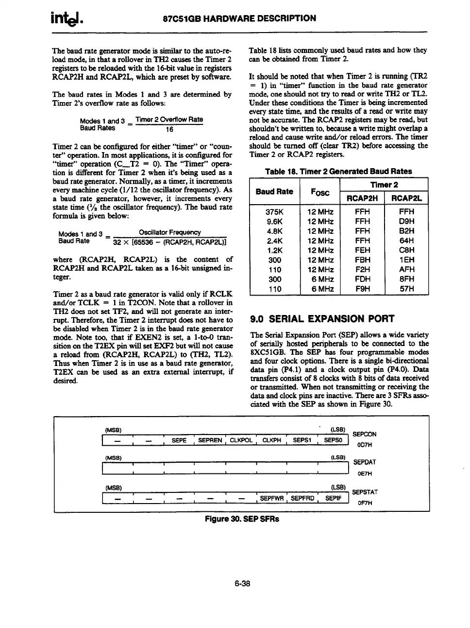
9.0 SERIALEXPANSIONPORT
The SerialExpansionPort (SEP)allowsa widevariety
of serially hosted peripheralsto be connectedto the
8XC51GB.The SEP has four programma
ble modes
and four clockoptions.There is a singlebi-directional
data pin (P4.1) and a clock output pin (P4.0). Data
transfersconsistof 8 clockswith 8bitsof dati received
or transmitted.Whennot transmittingor receivingthe
data andclockuinsare inactive.Thereare 3SFRSM
ciatedwiththe’SEPas shownin Figure30.
(MSB)
‘ (LSB) sEmN
—
SEPE
, SEPREN, CLKPOL, CLKPH
,
SEPS1
BEPSO
OD7H
(MSB)
(LSB)
6EPSTAT
—
—
t ,
, SEPFWR, SEPFRD
I
SEPIF
OF7H
I
Figure30.SEPSFRS
6-%