i@.
83C152 HARDWARE DESCRIPTION
LOGICAL I , I ~ I , I , I o I o I
VALUE :
MANCHESTER :
ENCODING I
,
l~rJjL
--lj
I
,
I ,
J
---
1 . . . ‘
----
-..
---
-.. .
--- -.. .
I
,--
-,
—
‘“l “ BIT TIME
“l”’
BITTIME—
RECEIVEDI ; : ;
DATAI , , ,
,1 *
,
,
,1 , ,
t
,
I
— 0’1“0BIT TIME
“O” BIT nME —
,
., ,
,* ,
,*,
1, I
,*,
,
,
,
nnnnnnM nnr nnrl~
,
‘1 ‘
i
RECEIVEDI ; ; ;
,1
DATAI , , ,
,*
11
.-. ------
,1 ,
270427-24
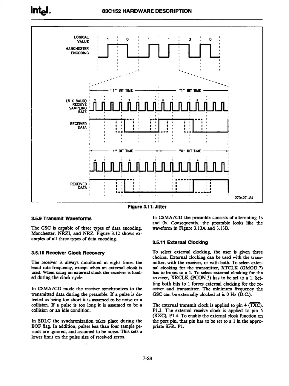
Figure 3.11. Jitter
3.5.9 Transmit Waveforms
The GSC is
capable of three types of data encoding,
Manchester,NRZI, and NRZ. Figure 3.12shows ex-
~Ples of a three types of data encoding.
3.5.10
Receiver Clock Racovery
The
receiver is always monitored at eight times the
baud rate frequency,except wherean externalclock is
used.Whenusingan external
clock the receiver is load-
ed
duringthe clock cycle.
In CSMA/CD mode the receiversynchronizesto the
transmitteddata duringthe preamble.If a pulseis de-
tectedas beingtoo short it is assumedto be noiseor a
collision.If a pulse is too longit is assumed to be a
collisionor an idle condition.
In SDLC the synchronizationtakes place during the
BOFflag.In addition,pulseslessthan four samplepe-
riodsare ignored,and assumedto be noise.This sets a
lowerlimit on the pulsesize of receivedzeros.
In CSMA/CD the lmarnble consistsof akematin~ 1s
and 0s. Ccmaequm-tly,the preamble looks like-the
waveformin Figure3.13Aand 3.13B.
3.5.11
External Clocking
To selectexternal clocking,the user is given three
choices.External clockingcan be usedwith the trans-
mitter, with the receiver,or with both.To selectexter-
nal clockingfor the transmitter, XTCLK (GMOD.7)
hasto be set to a 1.To selectexternalclockingfor the
receiver,XRCLK (PCON.3)has to be set to a 1.Set-
tingboth bits to 1 forcesexternal clockingfor the re-
ceiver and transmitter. The minimumfrequencythe
GSCcan be externallyclockedat is OHz (D.C.).
Theexternaltransmit clockis appliedto pin4 (TXC),
P1.3. The external reseive clock is applied to pin 5
(RXC),P1.4.To enablethe externalclockfunctionon
the port pin, that pin has to be set to a 1in the appro-
priate SFR, P1.
7-39