in~.
83C152 HARDWARE DESCRIPTION
DCON.7 (DAS)- DestinationAddress Space- When
set, destinationofdata to k-etransferredis internaldata
memoryifautoincrementmodeis alsoset. If autoincre-
ment is not set the dcstinationwillbe oneofthe Special
FunctionRegisters.WhenDASis clearedthen the des-
tination is externaldata memory.
DCR - DeterministicResolution,see MYSLOT.
DEN - An akernate fiction of one of the pml 1pins
(P1.2). Its purposeis to enableexternal drivers when
the GSC is
transmitting data. This functionis always
activewhenusingthe GSCand if PI.2 is programmed
to a 1.
DM - DMA Mock seeDCONO.
DMA - Direct
Memory Access
modq seeTSTAT.
DONE - DMA donebit, see DCONO.
DPH - Data Pointer High, sn SFR that containsthe
high order byteof a generalpurposepointercalledthe
data pointer(DPTR).
DPL - Data PointerLow,an SFRthat containsthe low
order byte of the data pointer.
EDMAO - Enable DMA Channel O interrupt, see
IEN1.
EDMA1
- Enable DMA channel 1 interrupL see
IEN1.
EGSRE - Enable GSC Receive Error interrupt, see
IEN1.
EGSRV - Enable GSC Receive Valid interrupt, see
IEN1.
EGSTE - Enable GSC Transmit Error interrupGsee
IEN1.
EGSTV- Enable GSC Transmit Valid interrupt, see
IEN1.
EOF - A generalterm used in serial communications.
EOF stands for End Of Frame and signitieswhenthe
Isst bits
ofdataaretransmi
ttedwhenusingPacketized
data.
ES-
EnableLSCSeMce interrupt, see IE.
ETO- EnableTimerOinterrupt, see IE.
ET1 - EnableTimer 1interrupL see IE.
EXO- EnableExternalinterrupt O,see IE.
EXl - EnableExternalinterrupt 1,see IE.
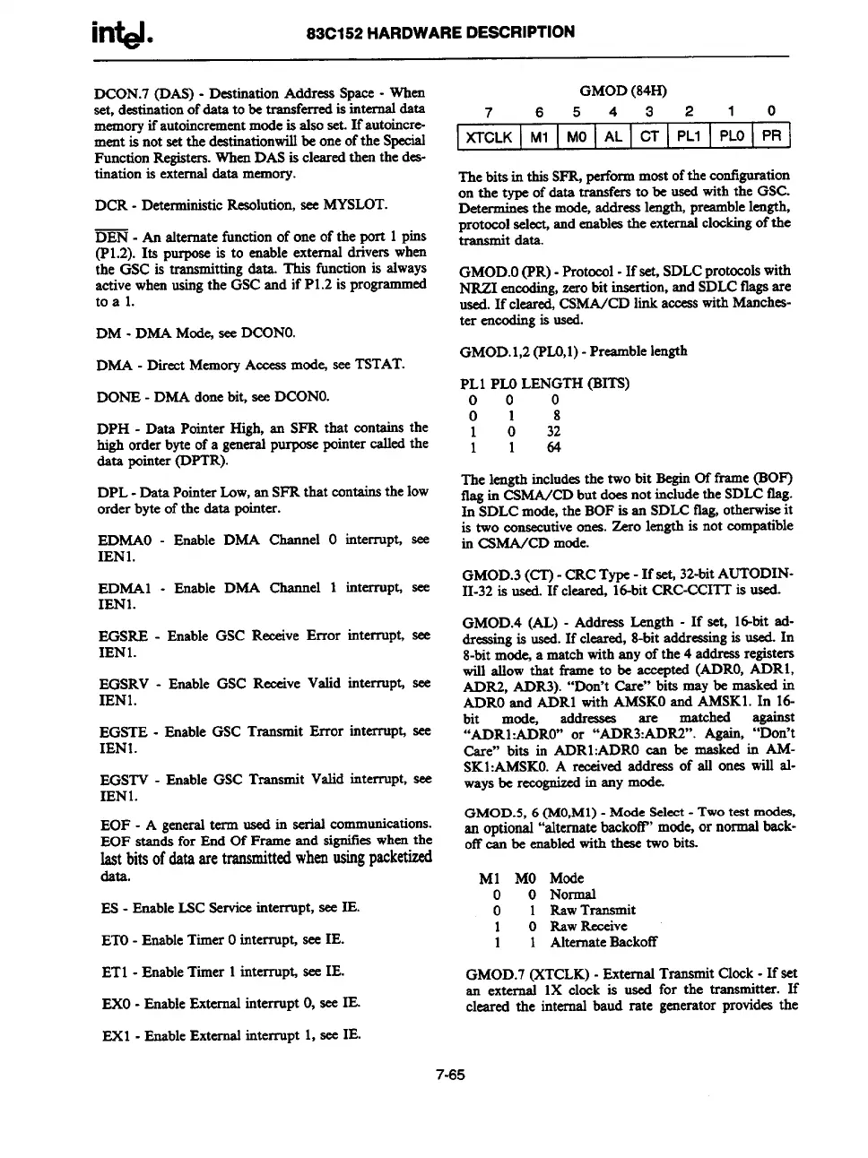
GMOD(84H)
7
6543210
XTCLK
Ml MO AL
CT
PL1 PLO
PR
Thebits in this SFR,performmostofthe configuration
on the type of&ta transfersto be usedwith the GSC.
-mines the mode,addresslength,preamblelength
protocolselect,andenablesthe externalclockingofthe
transmit data.
GMOD.O(PR)- Protocol-If set, SDLCprotocolswith
NRZI encoding,zerobit insertion,and SDLCflagsare
used.If cleared,CSMA/CDlink accesswithManches-
ter encodingis used.
GMOD.1,2(PLO,l)- Preamblelength
PL1 PLOLENGTH(BITS)
000
018
1 0 32
1164
The length includesthe two bit BeginOf frsme (BOF)
flagin CSMA/CDbut doesnot includetheSDLCflag.
In SDLCmode,the BOFis an SDLCtlag,otherwiseit
is two consecutiveones.Zero lengthis not compatible
in CSMA/CD mode.
GMOD.3(CT)- CRCType-If set, 32-bitAUTODIN-
11-32is used.If cleared, 16-bitCRC-CCITTis used.
GMOD.4 (AL) - Address Length - If set, 16-bitad-
&easingis used.If cleared,8-bitaddressingis used.In
8-bitmock a matchwithany of the 4 addressregistera
will allow that frame to be accepted (ADRO,ADR1,
ADR2, ADR3). “Don’t Care” bita may be maskedin
ADROand ADR1with AMSKOand AMSK1.In 16-
bit mode,
addresses are
matched
a-t
“ADR1:ADRO”or “ADR3:ADR2”. Again, “Don’t
Care” bits in ADR1:ADROcan be
maskedin AM-
SK1:AMSKO.A receivedaddress of all ones will al-
waysbe recognizedin any mode.
GMOD.5,6 (MO,M1)- Mode Select- TWOtest modes.
an optional“alternatebackotT’mode,or normalback-
offcan be enabledwiththese two bits.
Ml MO Mode
o 0 Normal
o
1 RswTransmit
1
0 RawReceive
1
1 AlternateBackoff
GMOD.7(XTCLK)- ExternalTransmitClock-If set
an external 1X clock is used for the transmitter. If
cleared the internal baud rate generator providesthe
7-65