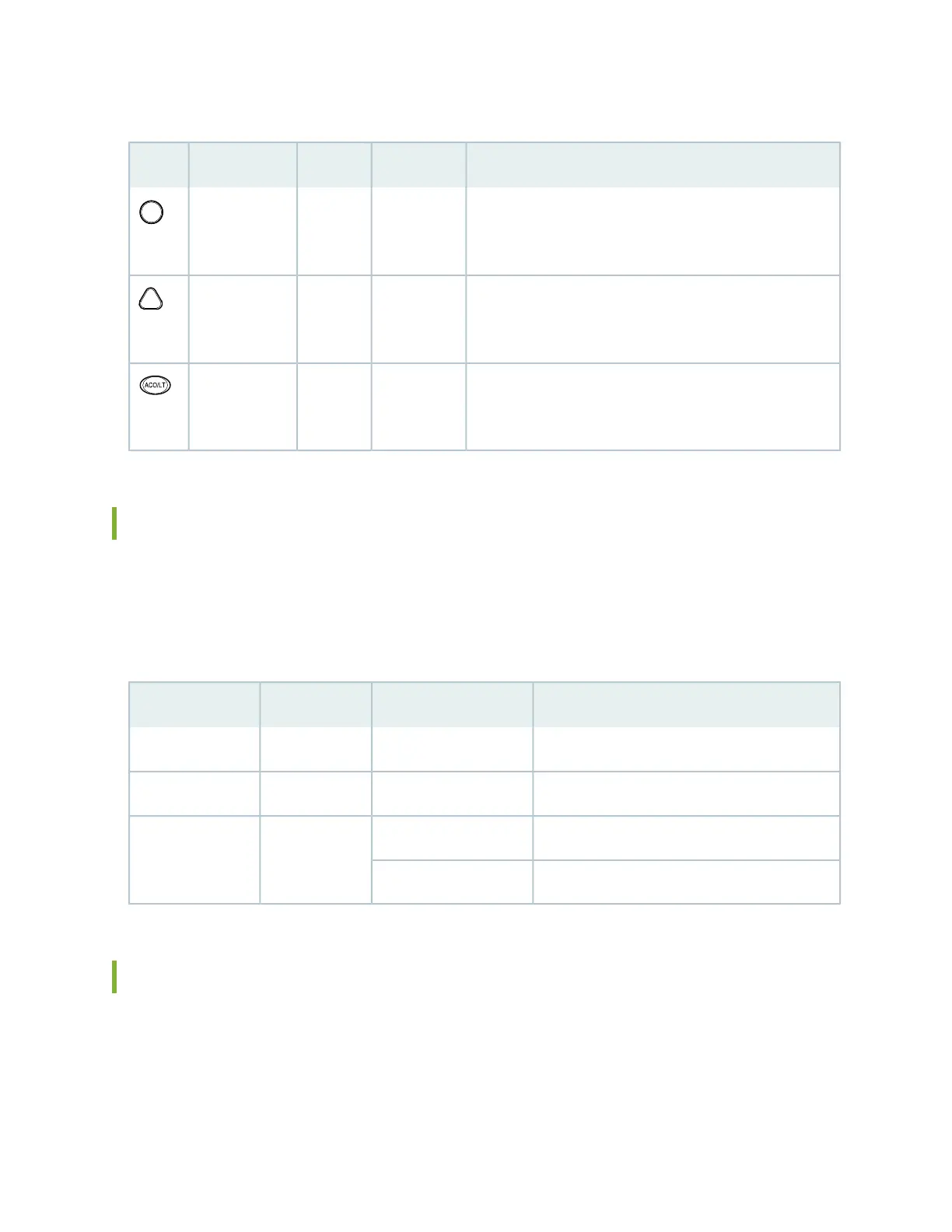
Table 6: Alarm LEDs and Alarm Cutoff/Lamp Test Button
DescriptionStateColorLabelShape
Critical alarm LED—Indicates a critical condition that can
cause the device to stop functioning. Possible causes include
component removal, failure, or overheating.
On steadilyRedMajor Alarm
Warning alarm LED—Indicates a serious but nonfatal error
condition, such as a maintenance alert or a significant
increase in component temperature.
On steadilyYellowMinor Alarm
Alarm cutoff/lamp test button—Deactivates major and minor
alarms. Causes all LEDs on the craft interface to light (for
testing) when pressed and held.
––ACO/LT
SRX5400 Services Gateway Craft Interface Host Subsystem LEDs
The host subsystem has three LEDs, located on the upper left of the craft interface, that indicate its status.
The LEDs labeled RE0 show the status of the Routing Engine and SCB in slot 0 . The LEDs labeled RE1
are disabled and have no function. Table 7 on page 35 describes the functions of the host subsystem LEDs.
Table 7: Host Subsystem LEDs
DescriptionStateColorLabel
Host is functioning as the master.On steadilyGreenMASTER
Host is online and is functioning normally.On steadilyGreenONLINE
Host is installed but the Routing Engine is offline.On steadilyRedOFFLINE
Host is not installed.Off
SRX5400 Services Gateway Craft Interface Power Supply LEDs
Each power supply has two LEDs on the craft interface that indicate its status. The LEDs, labeled 0 through
3, are located near the middle of the craft interface next to the PEM label. Table 8 on page 36 describes
the functions of the power supply LEDs on the craft interface.
35

 Loading...


