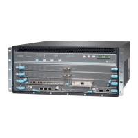
AUX—Connects the Routing Engine to a laptop, a modem, or another auxiliary device through
a cable with an RJ-45 connector.
CONSOLE—Connects the Routing Engine to a system console through a cable with an RJ-45
connector.
ETHERNET—Connects the Routing Engine through an Ethernet connection to a management
LAN (or any other device that plugs into an Ethernet connection) for out-of-band management.
Cables and connectors
•
RESET button—Reboots the Routing Engine when pressed
•
ONLINE/OFFLINE Button—Not supported in the current release
Controls
Front panel slot in an SCB installed in:
•
SRX5400: Bottom slot 0
•
SRX5600: Bottom slots 0 or 1
•
SRX5800: Center slots 0 or 1
NOTE: The services gateway host subsystem Routing Engine must be installed in the SCB
in slot 0. A Routing Engine installed in an SCB in slot 1 only enables dual control links in
chassis cluster configurations.
Supported Slots
90 WPower Requirement
Approximately 2.4 lb (1.1 kg)Weight
HDD LED:
•
Blinking green–The Routing Engine hard disk is functioning normally.
MASTER LED:
•
Blue–The Routing Engine is Primary.
NOTE: The SRX5400, SRX5600, and SRX5800 Services Gateways do not support a secondary
or backup Routing Engine, so the MASTER LED should always be lit.
OK/FAIL LED, one bicolor:
•
Off–The Routing Engine is operating normally.
•
Red–The Routing Engine has failed and is not operating normally.
ONLINE LED:
•
Blinking green–The Routing Engine is coming online.
•
Steady green–The Routing Engine is functioning normally.
LEDs
73

 Loading...