Keyscan Technical Guide (PC109x - 04.12)
119
Figure 90 - Communication LEDs on CPB-10-2
Communication LEDs
H1
B LED
RX
LED
CPB-10-2
J1
GND TD RD DCD
TO PC
GND R T B DTR CTS
M M M
TX
LED
KI-00190E-07-11
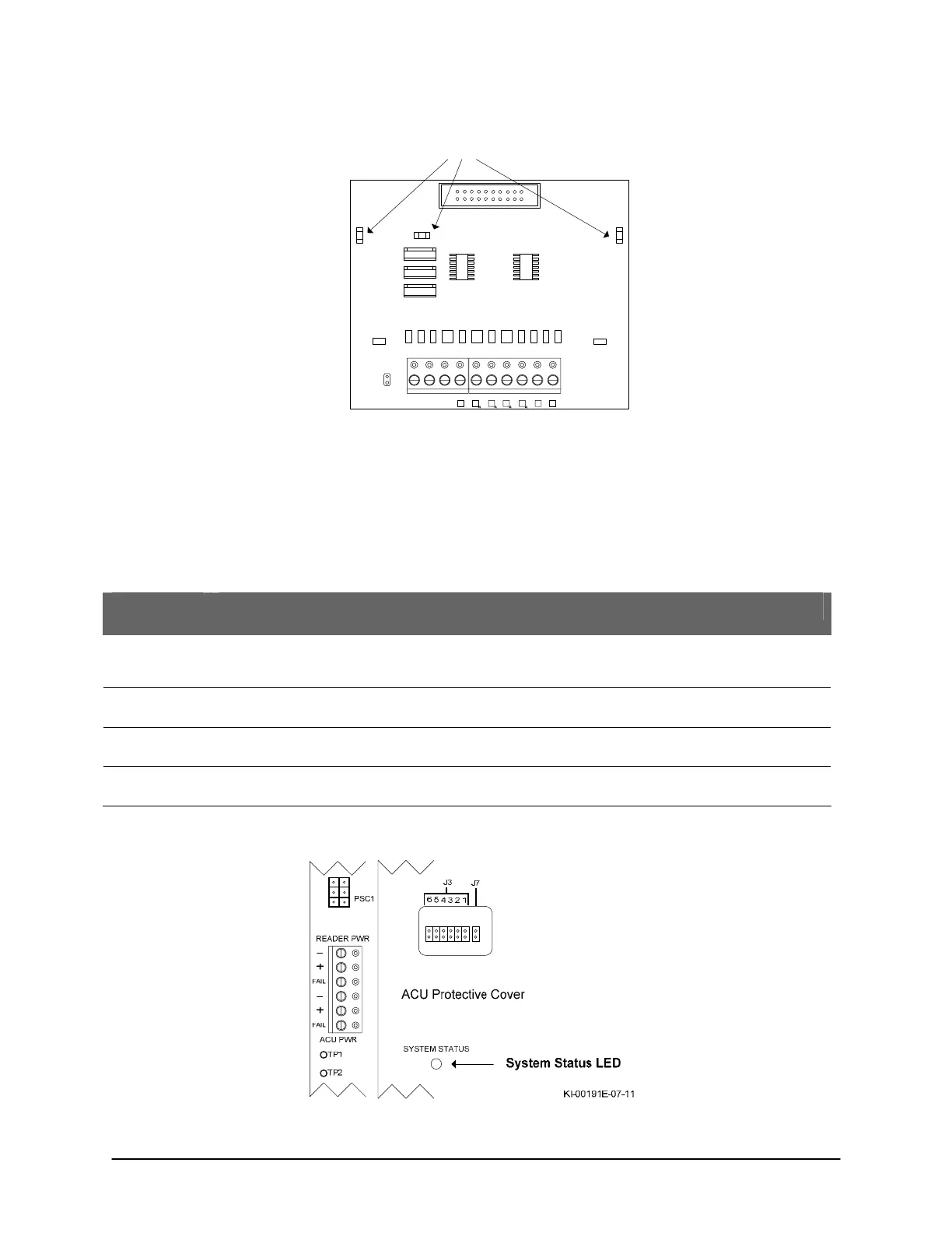
System Status LED
The System Status LED is multi-color – red, amber and green – indicating the current system status as
outlined. The control board also has a piezo that beeps under certain LED states.
Table 18 - System Status LED
LED
Color/State
System Status
Red – solid The main processor is held in reset and not operating. This can be caused by a jumper installed on J6 or by
the main processor supervisory circuit if critical PCB voltages are not within normal operating parameters.
The on-board piezo emits a steady tone while in this mode.
Red – flashing The CA or EC control board is in clear memory mode. The on-board piezo emits a cycle of 2 short beeps and
then a pause while the control board is in this mode.
Amber – solid The CA or EC control board has not communicated to the Client software since its last system reset or clear
memory.
Green – solid The CA or EC control board has communicated to the Client software since its last system reset or clear
memory.
Figure 91 - Location of System Status LED
 Loading...
