Keyscan Technical Guide (PC109x - 04.12)
50
Terminate Auxiliary Outputs with Hardware/Alarms
Door and auxiliary inputs can be programmed to trip auxiliary output relays on an alarm event. This excludes
pre-alert relays. Auxiliary output relays can be connected to alarm panels, CCTV systems etc.
As an example, a forced entry detected by a door input could be programmed to trip an auxiliary output that
initiates a CCTV system to record the intrusion at the door.
Auxiliary output relays may also be used to control hardware with an associated time zone, such as scheduling
the locking/unlocking of a door, which does not have a reader, to a defined time zone.
Important
Do not assign a time zone to an auxiliary output if the output has previously been assigned to an alarm
event. The alarm has priority over the time zone.
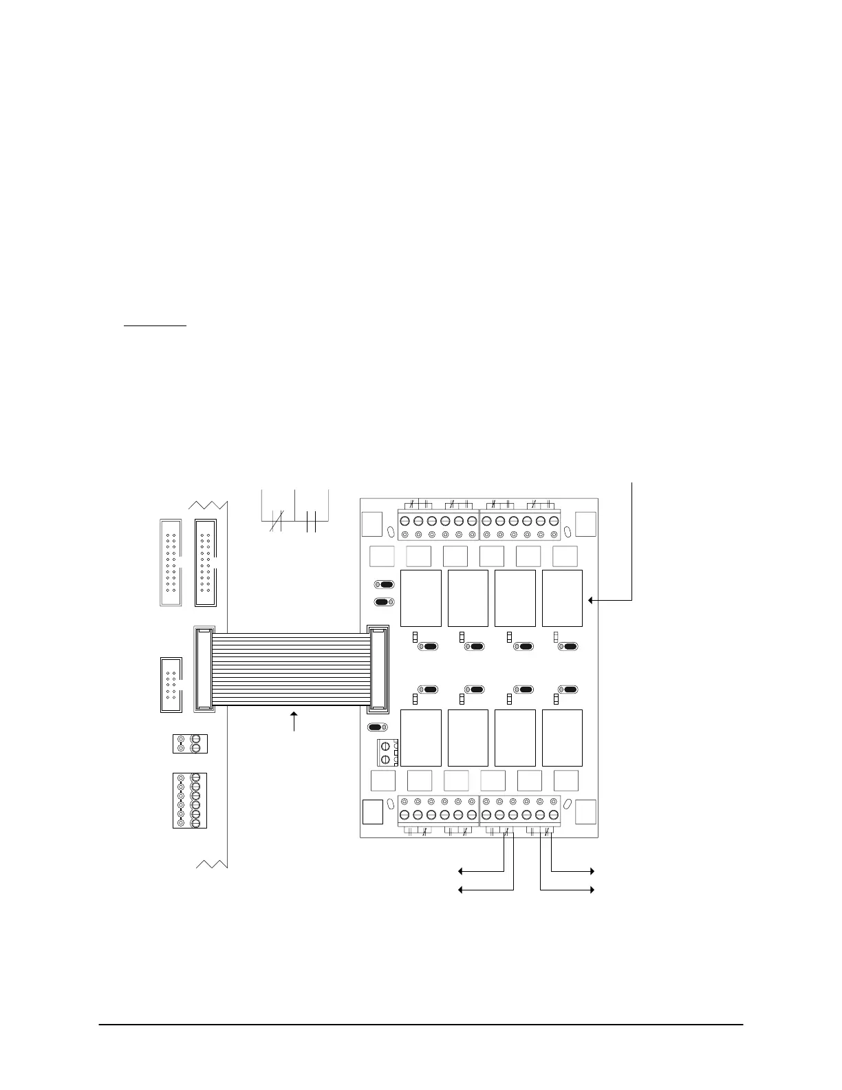
Figure 36 – Terminate Auxiliary Outputs CA250B
Normally
Closed
N.C.
Normally
Open
N.O.
alarm panel input
or
CCTV input
time zone
lock/unlock
CA250B
Control
Board
Cut View
OCB-8 ribbon cable
connects to CONTROL 1.
Door
Output
1
Door
Output
2
Aux
Output
1
Aux
Output
2
Aux
Output 4
or
HC 2
Pre-
Alert
Output
1
Pre-
Alert
Output
2
J1 J2 J3 J4
J5J6J7
J8
12V
ACU EXT
PWR
Normal
Reversed
J1
to
J8
K1
K2 K3 K4
K5K6K7K8
GND
red stripe
OCB-8
J9
Aux
Output 3
or
HC 1
When OCB-8 connected to CA250B
Relay 5 = Aux Output 3 or HC Output 1
Relay 6 = Aux Output 4 or HC Output 2
Do not use relays for both functions.
OCB-8
Relays
CONTROL 2
RS-232 (COM4)
CTS
CONTROL 4
DTR
DCD
RD
TD
GND
OCB-8 powered
through ribbon
cable with J9 set
to ACU PWR.
TAMPER TB3
SWITCH
+
-
KI-00139E-07-11
 Loading...
