Keyscan Technical Guide (PC109x - 04.12)
158
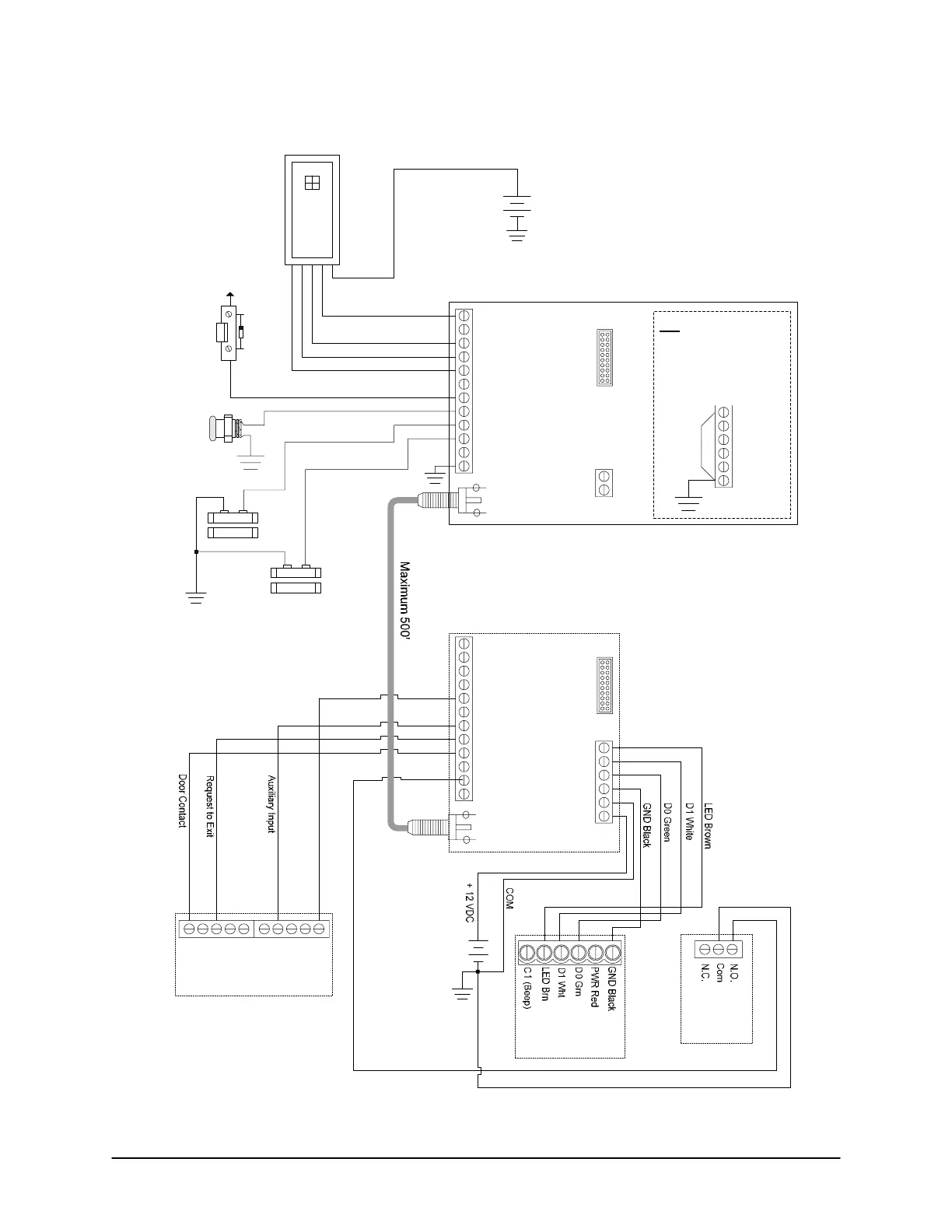
Figure 121 – CWIEEX2 Coaxial Connections – (Firmware Version 6.00 or Higher)
BLK GND
LED +
Brn LED
Wht D1
Grn D0
Red +5V
RA2 OC
RA1 D1
RA0 D0
RB5
RB4
GND
-
12VDC
+
H1
reader
+12 VDC
Data GND
White Data 1
Green Data 0
LED
Red +12VDC
CWIEEX-
Tx
Transmitter
Request to Exit Input N.O.
Door Contact Input N.C.
Auxiliary Input N.C.
Door Unlock Output
Blk GND
LED +
Brn LED
Wht D1
Grn D0
Red +5V
RA2 OC
RA1 D1
RA0 D0
RB5
RB4
GND
LED BRN
D1 WHT
D0 GRN
Data GND
-
12VDC
+
H1
CWIEEX-
Rx
Receiver
+
DC Supply (local)
-
+
DC Supply
-
Door
1212 1234
Control Board Inputs
Exit Auxiliary
for Communications Failure Output
connect to an open Auxiliary Input
CWIEEX Transmitter draws power from CWIEEX Receiver via coax cable.
All devices connected to CWIEEX Transmitter require independent local power
supply with sufficient amps. (CWIEEX Transmitter may be connected to local
supply if desired.)
Baud
19,200
ACU
Lock Relay
Diagram shows lock relay in ‘fail safe’. For ‘fail secure’ connect RB4 on receiver to N.C. on lock relay.
RB4
DCD
DTR
RX
TX
GND
Note
If experiencing communication
difficulties over longer cable
distances, set the baud to
9,600 by shorting RB4 to GND
on the CWIEEX transmitter.
Control Board
Reader
Terminal
KI-00225E-07-11
 Loading...
