Keyscan Technical Guide (PC109x - 04.12)
77
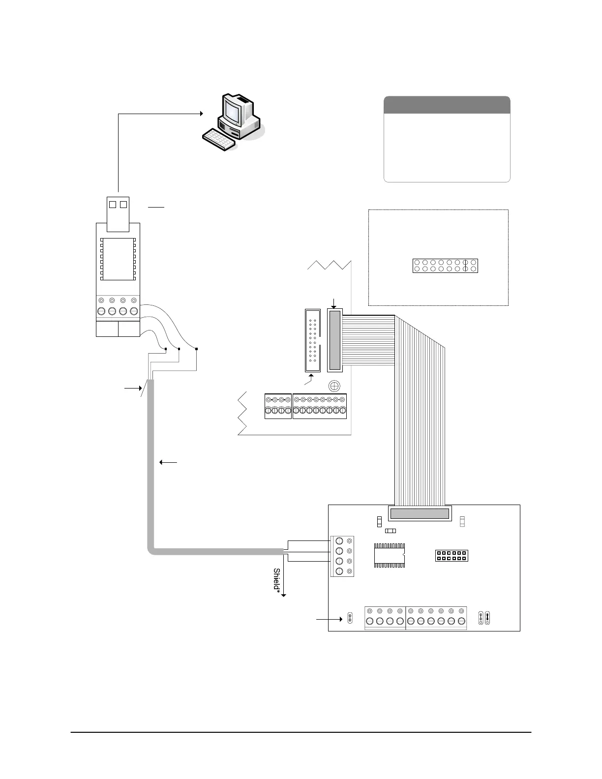
Figure 54 – Single ACU Communication - USB Adaptor/CB-485 (RS-232)
RS-232
22 AWG shielded cable
Maximum - 100 ft (30 M)
PC with
Communication Manager
- USB Adaptor (USB-SER)
- RS-232 Data Cable
-CB-485
- Control Board
- PC (requires USB port)
- USB extension cable optional
Green
Black
use 3 loose
RS-232 wires
tape
back
shield
Green
Red
Black
Jumper ON J1
To USB port on PC
(may require USB
extension cable)
Red
Unused conductors
are taped back
separately.
Unused
conductors are
taped back
separately.
BRNWHTGRN WHT
+ TX - + RX -
485 OUT
485 IN
Note
USB communication is slower than direct
serial or NETCOM communication.
Do not connect USB adaptor to modem.
to ground lug
Common AUX Inputs - E
24
2322
2120191817
CPB/CB COMMS
(COM4)
Parts List
Control Board
(PC 109x)
Connect CB-485 ribbon cable to
CPB/CB MODULE on control board.
Jumper ON J16-G to activate
CPB/CB MODULE (H1).
SYSTEM CONFIG.
J16 - H
GABCDEF
H1
GND
CB-485
J1
RX
LED
TX
LED
TD
RD
NC
BRN WHT GRN WHT BRN WHTGRN WHT BLU WHT
RS485 IN RS485 OUT M
+-+-+-+-
Current Draw - 110 mA
Jumpers ON
Run
Run
Program
B LED
ECM/GCM MODULE
(COM2 & COM3)
H2
KI-00157E-07-11
* Insulate shield with PVC tubing such
as Alpha #16 or comparable insulator
and connect to ground lug.
 Loading...
