Keyscan Technical Guide (PC109x - 04.12)
83
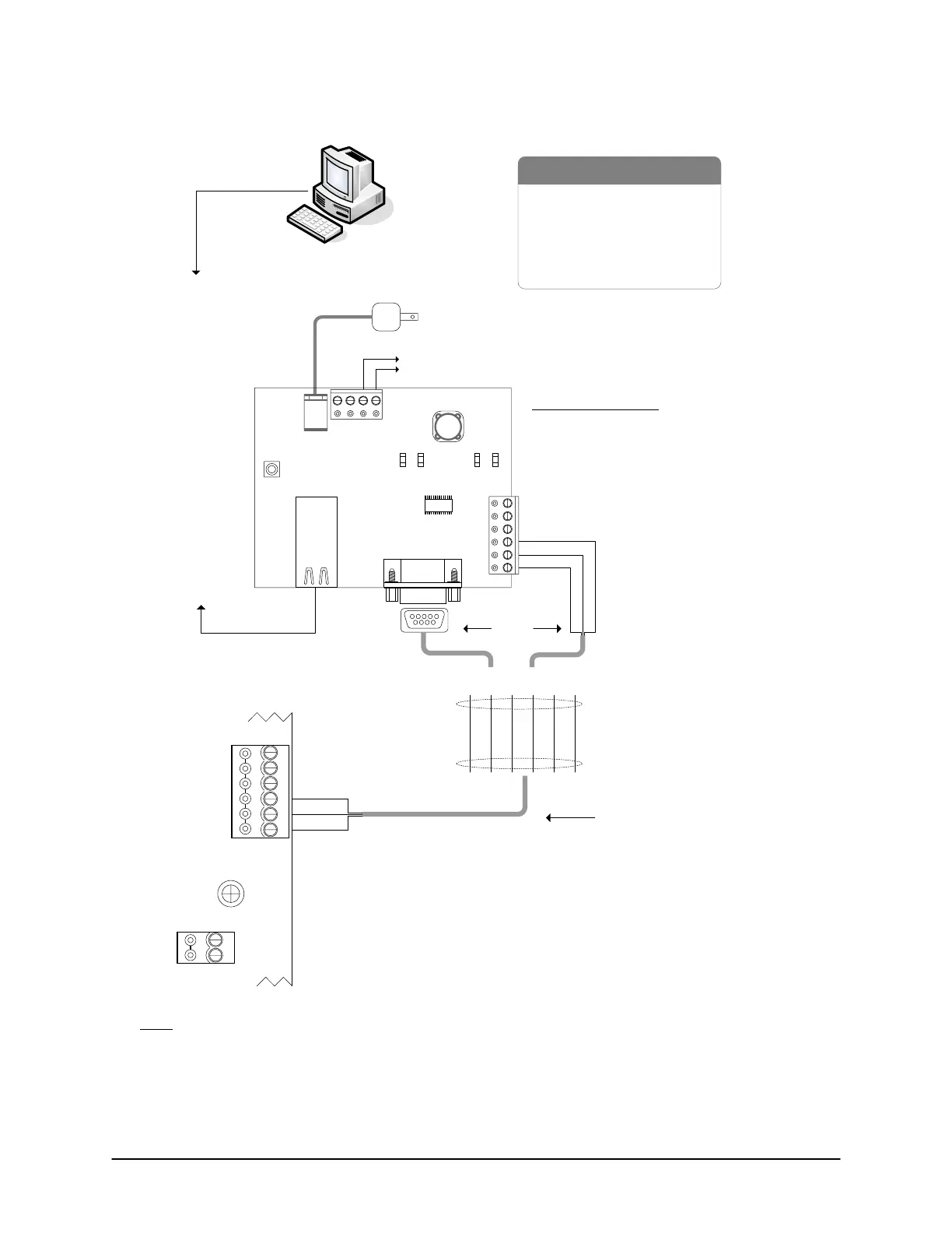
Figure 60 – Single ACU Communication - NETCOM2 or NETCOM6
Host PC with
Communication Manager
- RS-232 Data Cable
- Control Board
-PC
- NETCOM2 or NETCOM6
- 10/100 Base-T Cable
via shielded 6-wire cable
Brown
Shield
Green
Black
Red
White
10/100 Base-T
12 VDC Power Adaptor (NETCOM2H or NETCOM6H)
to
network
12 VDC to DPS15 (NETCOM2 or NETCOM6)
Green
Red
Black
Either
or
Use either the 9-pin connector
or the terminal block.
Do not use both to connect to
the control board.
to
network
NETCOM LED Legend
- RS-232 indicates 9-pin terminal connected
- RX LED indicates PC polling ACU/ECU
- TX LED indicates ACU/ECU replying to PC
- ON LED indicates unit receiving power
RS-232
22 AWG shielded cable
Maximum - 100 ft (30 m)
GND
RS-232 (COM4)
Control Board
(PC 109x)
Green &
Shield
Black
Brown & White
not used. Tape
back separately.
TD
RD
DCD
DTR
CTS
Red
IOCB (COM1)
RX
TX
Parts List
Ensure J16 - F & G
Jumpers OFF
12VDC
power adaptor
12VDC
+-
Reset
Button
RJ45
Jack
9-pin Male
Connector
RS-232RX TX ON
LEDsLEDs
GND
TD
RD
DTR
DCD
I/O
NETCOM2 or
NETCOM6
Current Draw
270 mA
KI-00163E-07-11
Note
If the NETCOM2 or NETCOM6 is mounted in the metal enclosure, the shield of the serial cable may be
connected to GND as shown. If the NETCOM2 or NETCOM6 is mounted outside the metal enclosure the
shield must be insulated and connected directly to the metal enclosure ground lug. See Grounding
Communication Cable Shield.
 Loading...
