Keyscan Technical Guide (PC109x - 04.12)
55
Function Mode Jumper # Settings
Enable Clear Memory Enables the Clear Memory jumper J1 to reload
factory defaults
H 1
Disable the Clear Memory jumper J1 H 0
Communication Terminal Block Activation
RS-232 For direct serial communication connect to RS-
232 (COM4) - TB4 terminal block
F G 0 0
CB-485/CPB-10-2 CB-485 and CPB-10-2 communication via CPB/CB
MODULE (COM4) - H1 terminal block
F G 0 1
NETCOMP NETCOMP communication plugged directly into M1
on control board (COM4)
F G 1 0
NETCOMP – Program mode Program mode for NETCOMP plugged into M1
(COM4)
F G 1 1
ECM or GCM Connect to ECM/GCM MODULE (COM2 & COM3)
terminal block. The ECM/GCM MODULE is an open
terminal block and does not require setting pins F
& G nor is it affected by any of the communication
configuration settings above.
n/a
Alternate Panel Serial # Selection Leave on Default Serial # setting – pins OFF –
unless prompted in the Client software when
inputting panel data in the Site Unit Setup screen.
A B 0 0
Alternate Serial # 1 A B 0 1
Alternate Serial # 2 A B 1 0
Alternate Serial # 3 A B 1 1
Accessibility HC Relay – Enable All Cards Off – only cards designated with accessibility
feature pulse HC relay
D 0
On – all cards pulse HC relay D 1
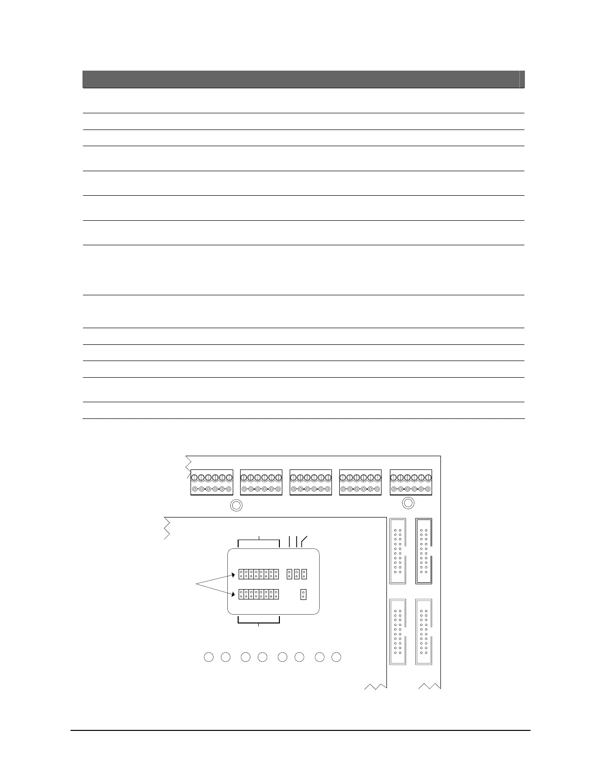
Figure 40 – System Configuration J16 Location
J16
J16
1
2
345678
ABCDEFGH
COMMUNICATION STATUS
TD1 RD1 TD2 RD2 TD3 RD3 TD4 RD4
READER 1READER 2READER 3READER 4READER 5
CONTROL 2
CONTROL 4
CONTROL 3
CONTROL 5
J1J6 J17
Protective ACU
Cover
Cut View of CA8500B
Location of J16 is the
same on all CA & EC
control boards.
System Configuration
Jumpers J16
KI-00143E-07-11
 Loading...
