Keyscan Technical Guide (PC109x - 04.12)
95
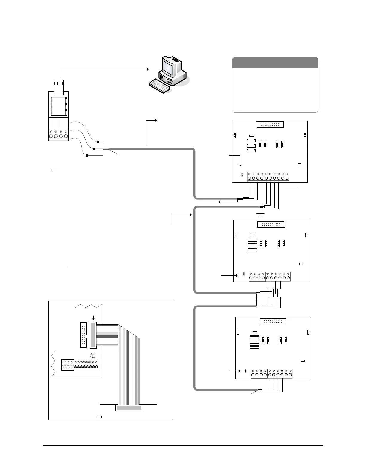
Figure 72 – Multiple ACU Communication - USB Adaptor/CPB-10-2
- PC (with USB port)
- 22 AWG 4 conductors shielded cable
- Control Board
- CPB-10-2
- USB Adaptor (USB-SER)
- USB extension cable optional
Brown & White
not used. Tape
back
separately.
Jumper
OFF J1
Green
Red
Black
GND
R
T
B
Shield
GND
R
T
B
GND
R
T
B
GND
R
T
B
Shield
Tape back
shield
CPB-10-2
- supports parallel and star communication
(diagram shows CPB-10-2 in parallel communication)
- maximum distance 1st to last CPB-10-2 - 4000 ft (1219 m)
- maximum distance between CPB-10-2s - 2000 ft (609 m)
EIA/TIA 562
Signal
to USB port (may require
USB extension cable)
PC with
Communication
Manager
RS-232
22 AWG shielded cable
Maximum - 100 ft (30 m) @
9600 BPS
Green
Black
Use 3 loose
RS-232 wires.
Red
Tape back shield.
Unused conductors
taped back separately.
Note
USB (RS-232) communication is
slower than direct serial or
NETCOM communication. Do not
connect USB adaptor to modem.
Shield*
to ground lug
B LED
Connect CPB-10-2 ribbon
cable to CPB/CB MODULE
terminal on control board.
Common AUX Inputs - E
CPB/CB MODULE
(COM4)
CPB-10-2
Control
Board
(PC 109x)
Parts List
Legend
GND = Ground
R = Rx
T = Tx
B = Busy Line
Important
Jumper ON
J16 – G to
activate CPB/
CB MODULE
(H1) terminal.
H1
BRN
WHT
GRN
WHT
+ TX - + RX -
485 OUT 485 IN
RX
LED
TX
LED
Current Draw 40 mA
CPB-10-2
GND
TD
RD
DCD
T
B
GND
R
DTR
CTS
J1
TO PC
RX
LED
TX
LED
Current Draw 40 mA
CPB-10-2
GND
TD
RD
DCD
T
B
GND
R
DTR
CTS
J1
TO PC
RX
LED
TX
LED
Current Draw 40 mA
CPB-10-2
GND
TD
RD
DCD
T
B
GND
R
DTR
CTS
J1
TO PC
Jumper ON J1
(First & Last
CPB10-2)
Jumper ON J1
(First & Last
CPB10-2)
H2
KI-00175E-07-11
* Insulate shield with PVC tubing such
as Alpha #16 or comparable insulator.
 Loading...
