Keyscan Technical Guide (PC109x - 04.12)
42
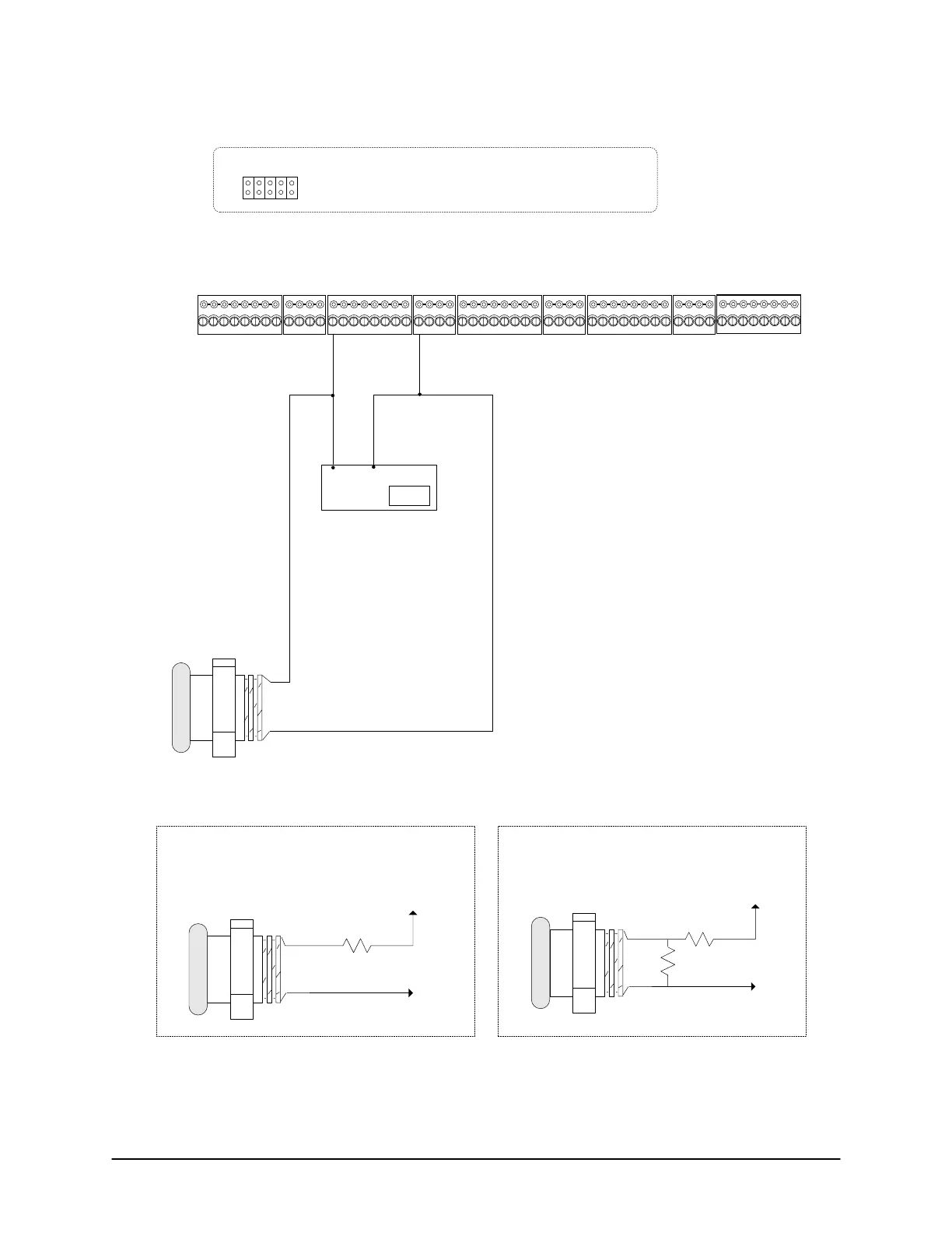
Figure 29 – Terminate Input Wiring RTE - PIR & Push Button
Notes
Diagram illustrates CA8500B. Connections
also apply to CA250B & CA4500B.
- CA250B – up to 2 Request to Exits
- CA450B – up to 4 Request to Exits
- CA8500B – up to 8 Request to Exits
Lens
NO
COM
PIR (Request To Exit)
NO = Normally Open
PIR
Motion Sensor RTE (Request to Exit) – ½ second
pulse
Determines the amount of time the output relays
will energize when motion is detected.
RTE
Push Button
COM
NO
NO = Normally Open
“Two devices wired in
parallel to each other”
J18 – Jumper 5 = Off
Jumper 4 = On
Single end of line supervision
to Request
to Exit
to Common Return
J18 Jumper 5 & 4 = On
Double end of line supervision
1K
3K
COM
NO
to Request
to Exit
to Common Return
1K
COM
NO
Note
If using supervision, it is only required on the device farthest from the ACU
terminal. Example shows supervision on RTE Push Button.
No supervision
J18 Jumper 5 & 4 = Off
Cut View of CA8500B
Door Inputs - A RTE Inputs - B
8
J18 – pins 5 & 4 set supervision type (Jumper setting
applies to all Door Inputs, RTE Inputs, and AUX Inputs.)
76
54321
Common
8
76
54321
AUX Inputs - C
8
76
54321
Common Common AUX Inputs - D
16
1514
131211109
Common
AUX Inputs - E
24
2322
2120191817
J18
54321
KI-00132E-07-11
 Loading...
