Keyscan Technical Guide (PC109x - 04.12)
49
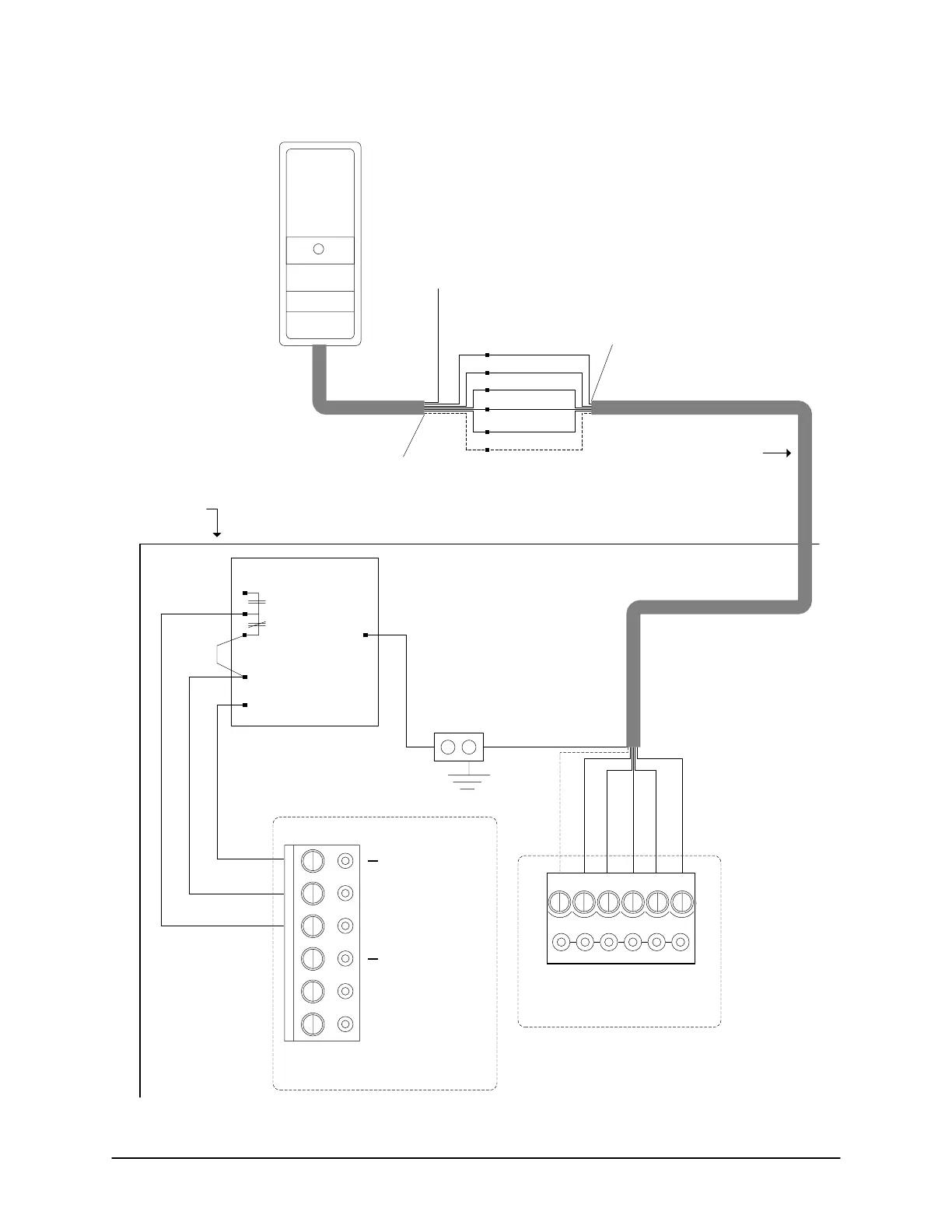
Figure 35 – Terminate Reader Wiring
Shield not
connected.
Isolate with
electrical tape.
3 pairs shielded
22 AWG or 18 AWG
500 ft (152.4 m) maximum
Reader terminal on control board
External DC
Supply
Red (+ VDC)
Black (-)
Proximity
Reader
Shield
Ground
Lug
LED
D1 (White)
D0 (Green)
PWR (Red)
GND (Black)
Enclosure
KEYSCAN
Cable in through knockout.
READER PWR
ACU PWR
+
Power terminal on control board
Blue used for pre-alert
otherwise isolate and tape
back.
Orange not
used. Isolate
and tape back.
Shield not
connected.
Isolate with
electrical tape.
LED (Brown)
D1 (White)
D0 (Green)
PWR (Red)
GND (Black)
Pre-alert (Blue)
Orange
FAIL
+
FAIL
EGND
AC Fail
Pre-alert (Blue)
DC Output 12V
-
+
N.C.
N.O.
Energized when AC
present.
LED D1
WHT
D0
GRN
PWR
RED
GND
BLK
C1
(BEEP)
KI-00138E-07-11
 Loading...
