Keyscan Technical Guide (PC109x - 04.12)
48
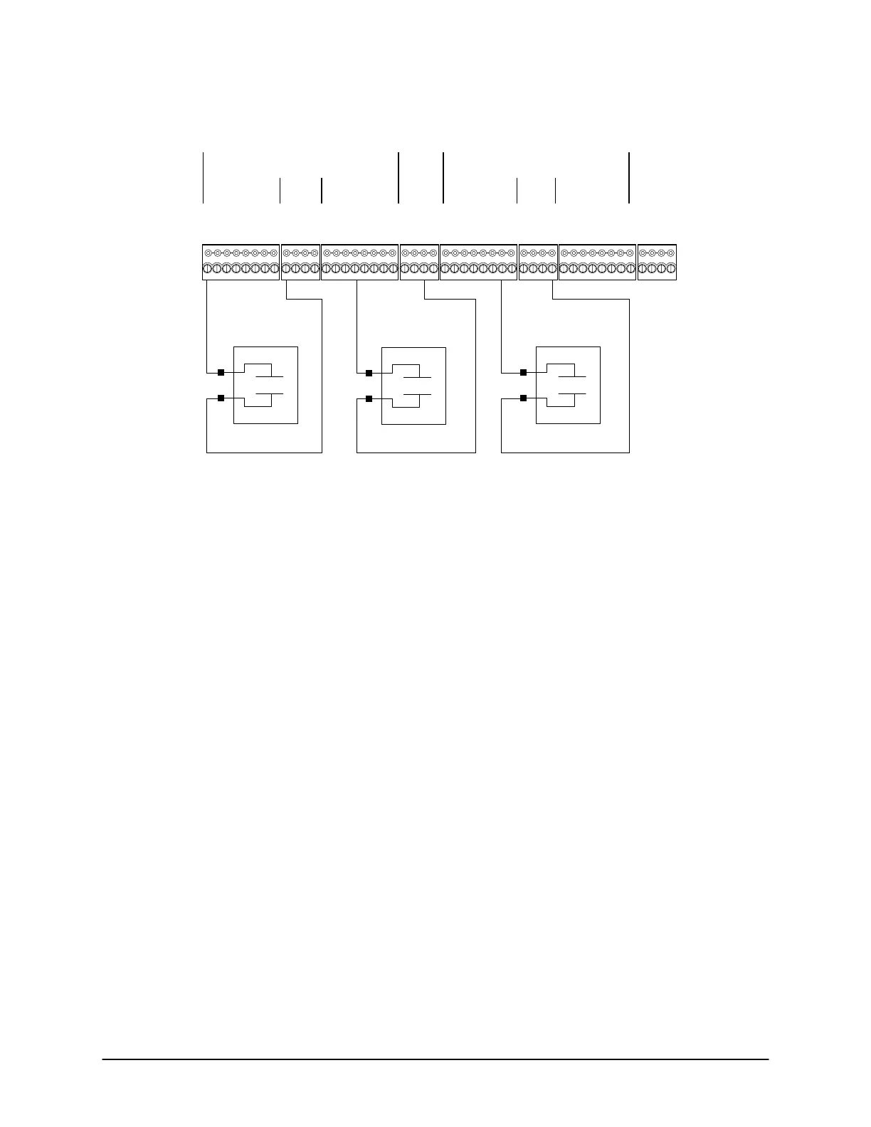
Figure 34 – Terminate Floor Input Wiring EC2500B
Floors 1 - 8
Floors 9 - 16
Floors 1 - 8
Floors 9 - 16
Dry Contact
Relay
N.O.
Elevator B
Call Button Status
7 of 16
Normally Open
Dry Contact
Relay
N.O.
Elevator A
Call Button Status
1 of 16
Normally Open
Dry Contact
Relay
N.O.
Elevator A
Call Button Status
12 of 16
Normally Open
Cut View of EC2500B
Elevator A - 16 Floor Status Inputs
Elevator B - 16 Floor Status Inputs
Floor monitoring inputs (separate dry contacts) provided by 3
rd
party elevator company.
Door Inputs - A RTE Inputs - B
8
76
54321
Common
8
76
54321
AUX Inputs - C
8
76
54321
Common
Common AUX Inputs - D
16
1514
131211109
Common
KI-00137E-07-11
Terminate Reader Wiring at ACU
For reader cable, use six (6) conductors 22 AWG shielded (6 conductors 18 AWG shielded for elevators) or a
cable with overall shielding. Use 18 AWG for current demanding readers such as the Indala PX620 or the
HID5375. The shielding wire must be connected to the earth ground lug at the ACU, isolated and taped at the
reader. The maximum reader distance is 500 feet (152.4 m) from the ACU when transmitting a Wiegand signal.
If the distance is greater than 500 feet (152.4 m), install one WIEEX2 per reader, which extends the distance
to 4000 feet (1219.2 m). See Appendix F –WIEEX2 & CWIEEX2 on page 154.
Reader Wiring
• Red – Positive DC Power. For readers that draw more current, connect the red wire directly to the power
supply.
• Black – Ground (GND)
• Brown – Light Emitting Diode (LED) on reader
• Green – Data output bit 0
• White – Data output bit 1
• Blue – optional pre-alert (reader beeper)
For specific reader wiring review the appendices listed in the Table of Contents.
 Loading...
