Keyscan Technical Guide (PC109x - 04.12)
148
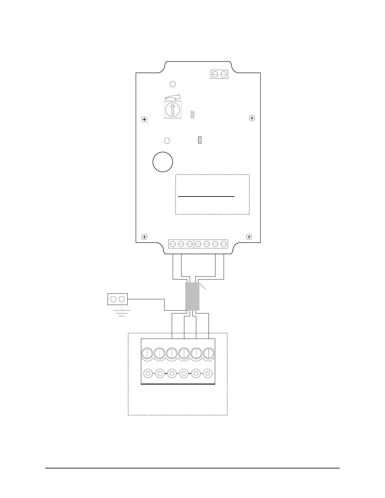
Figure 114 – K-RX Single Reader Connections - Channel B to ACU
RANGE
+
-
GND
ANT
J1
Open: Buttons 1/2
Closed: Buttons 3/4
J5
LED/Beeper
Control
D6
D7
+12V
GND
GND
AD0
AD1
BD0
BD1
BUZ1
Shield
ACU Ground Lug
White
Green
Red
Black
1
2
3
4567
Black
Red
Green
White
Receiver wired for Channel B
Active Transmitter Button
- Jumper OFF J1 – Button 2
- Jumper ON J1 – Button 4
3 pairs shielded 18 AWG
maximum 500 ft (152.4 m)
For single channel
application Blue and
Brown not used.
Isolate and tape
back separately.
Shield – Isolate
and tape back.
Reader terminal on control board
LED D1
WHT
D0
GRN
PWR
RED
GND
BLK
C1
(BEEP)
KI-00218E-07-11
 Loading...
