Keyscan Technical Guide (PC109x - 04.12)
35
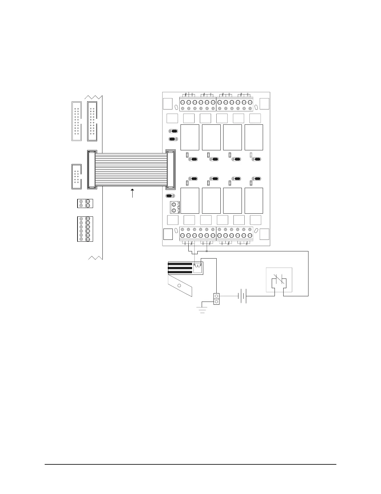
Figure 23 – Terminate Lock Wiring CA250B
12 VDC+
Com
CA250B
Control
Board
Cut View
+
-
DC
Supply
OCB-8 ribbon cable
connects to CONTROL 1
terminal.
Door
Output
1
Door
Output
2
Aux
Output
1
Aux
Output
2
Aux
Output 4
or
HC 2
Pre-
Alert
Output
1
Pre-
Alert
Output
2
J1 J2 J3 J4
J5J6J7
J8
12V
ACU EXT
PWR
Normal
Reversed
J1
to
J8
K1
K2 K3 K4
K5K6K7K8
GND
CONTROL 2
RS-232 (COM4)
CTS
Door # 1
Mag Lock
- Fail Safe -
to N.C.
Ensure all lock
hardware complies
with federal, state/
provincial, and
municipal fire codes.
red
stripe
OCB-8
J9
Fire Contact
Aux
Output 3
or
HC 1
N.C.
breaks on alarm
When OCB-8 connected to CA250B
Relay 5 = Aux Output 3 or HC Output 1
Relay 6 = Aux Output 4 or HC Output 2
Do not use relays for both functions.
Ground
Lug
CONTROL 4
OCB-8 powered
through ribbon cable
with J9 set to ACU
PWR.
DTR
DCD
RD
TD
GND
TAMPER TB3
SWITCH
+
-
KI-00126E-07-11
 Loading...
