Keyscan Technical Guide (PC109x - 04.12)
23
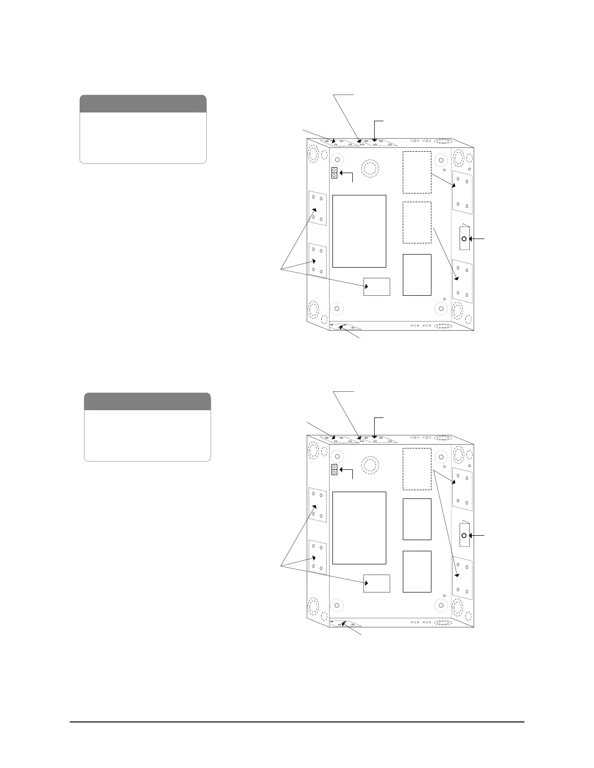
Figure 9 – CA4500 with Board Mounting Positions
Front View
Cover not shown
Tamper
Switch
1 x CA4500B control board
1 x OCB-8
1 x DPS-15 power supply
1 x metal enclosure
CA4500B
Control
Board
OCB-8
Optional
OCB-8
Locations
Optional
OCB-8
Locations
Ground Lug
Wireless NETCOM antenna
Wireless NETCOM or NETCOM
or MC9600
NETCOM*
or
CB-485
or
CB-485M
or
CPB-10-2
* NETCOM - for side mount, use
terminal block only, not 9-pin
male connector.
**DPS-15 must be connected to
TB1 on control board.
PC109x
Parts
DPS-15
power supply
Optional location for DPS-15 power supply**
KI-00112E-07-11
Figure 10 – CA8500 with Board Mounting Positions
Front View
Cover not shown
Tamper
Switch
1 x CA8500B control board
2 x OCB-8
1 x DPS-15 power supply
1 x metal enclosure
CA8500B
Control
Board
OCB-8
Optional
OCB-8
Locations
Ground Lug
Wireless NETCOM antenna
OCB-8
Wireless NETCOM or NETCOM
or MC9600
NETCOM*
or
CB-485
or
CB-485M
or
CPB-10-2
* NETCOM - for side mount, use
terminal block only, not 9-pin
male connector.
** DPS-15 must be connected to
TB1 terminal on control board.
PC109x
Parts
DPS-15
power supply
Optional location DPS-15 power supply**
KI-00113E-07-11
 Loading...
