Keyscan Technical Guide (PC109x - 04.12)
126
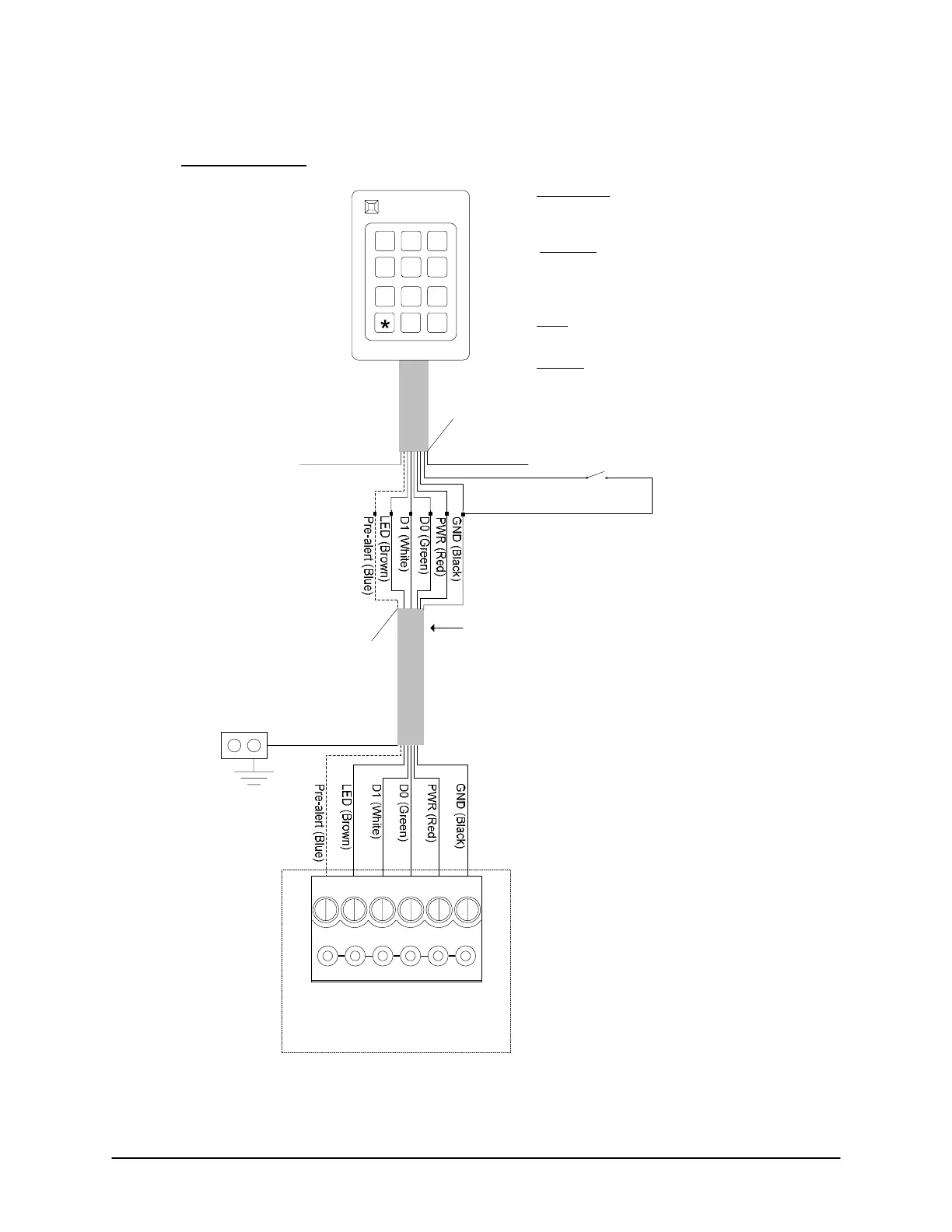
Figure 96 - Keyscan K-KPR SM
Shield not connected.
Isolate with electrical tape.
6 conductors – shielded 22 AWG
Maximum 500 ft (152.4 m)
May require 2 additional conductors
if using external pre-alert device.
Shield
ACU
Ground
Lug
Orange (Tamper)
- when using
an optional Tamper Switch (Normally
Closed) locally at reader, connect to GND Black
wire.
- when not using
Tamper Switch connect to GND
Black wire at reader.
Yellow
(Not used by
Keyscan.) Isolate
and tape back.
Purple (Read Mode)
- when not connected
, read mode set for secure
sector read only. Isolate and tape back. (This is
the recommended mode which offers higher
security.)
– when connected,
read mode set for secure
sector or CSN. If secure sector unrecognized,
subsequently reads the CSN sector of card.
Connect to GND Black wire at reader.
Purple
Orange
Shield not connected.
Isolate with electrical tape.
Optional Wiring
1 2 3
4 5 6
7 8 9
0 #
Diagram applies to
PC109x or newer
control board.
K-KPR Smart Versions
K-KPR-SM Mifare
K-KPR-SM/125
K-KPR-GOV
K-KPR-G/125
Reader terminal on control board
LED D1
WHT
D0
GRN
PWR
RED
GND
BLK
C1
(BEEP)
Blue used for pre-alert
otherwise isolate and tape
back.
If connecting external
sound device, see Pre-Alert
Relay Option or refer to
ACU cut sheet enclosed
with panel for ACU/OCB8
relay assignments.
Yellow
KI-00418E-11-11
 Loading...
