Keyscan Technical Guide (PC109x - 04.12)
90
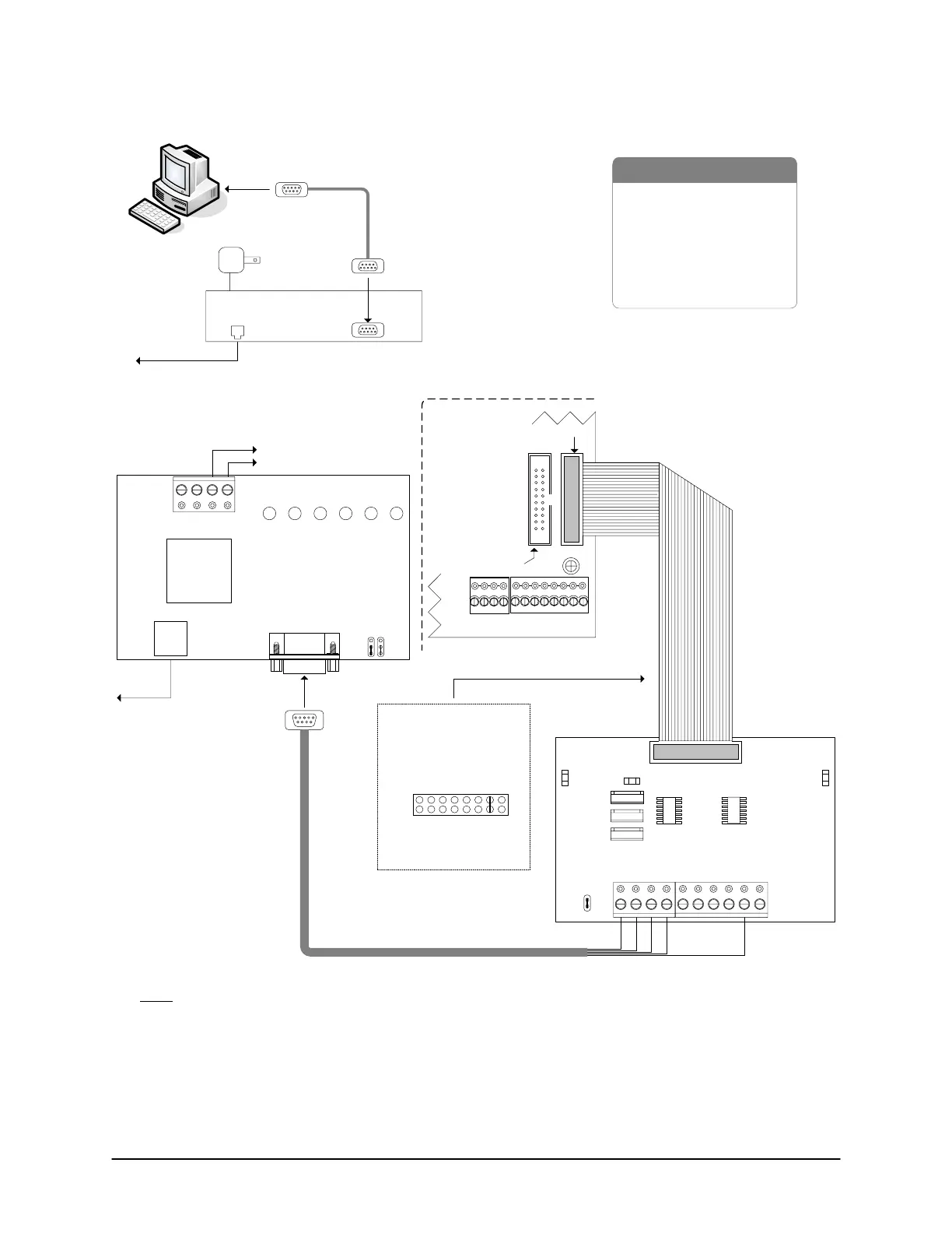
Figure 67 – Single ACU Communication - MC9600/MC33H/CPB-10-2
PC with
Communications
Manager
to Com
Port
RS-232
Modem
Cable
to
analog phone line
12VDC Adaptor
plug on reverse.
RJ 11
MC33H
External Host
Modem
to
analog
phone
line
Set
jumper
to DTE
MC33H jumper - DCE
- RS-232 Modem Cable
- RS-232 Data Cable
- Control Board
-MC9600
- MC33H Modem
- CPB-10-2
- PC (requires serial port)
- Dedicated Analog Phone Line
to 12VDC ACU power supply
Current Draw
300 mA
GND
MC9600
RX TX MRRIDCD
DCE
-+
12VDC
DTR
DTE
9-pin Male
Connector
RJ11
-
+
Shield
&
Green
Red
Black
White
Brown
to 9-pin
male
connector
Control Board
(PC 109x)
Common
AUX Inputs - E
24
2322
2120191817
CPB/CB MODULE
(COM4)
Parts List
Connect CPB-10-2 ribbon
cable to CPB/CB MODULE
on control board.
Jumper ON J16-G to
activate CPB/CB
MODULE (H1).
SYSTEM CONFIG.
J16 - H
GABCDEF
H1
GND
CPB-10-2
J1
RX LEDTX LED
TD RD DCD GND R T B DTR CTS
Current Draw - 40 mA
H2
ECM/GCM MODULE
(COM2 & COM3)
KI-00170E-07-11
Note
If the MC9600 modem is mounted in the metal enclosure, the shield of the serial cable may be connected
to GND as shown. If the MC9600 modem is mounted outside the metal enclosure, the shield must be
insulated and connected directly to the metal enclosure ground lug. See Grounding Communication Cable
Shield.
 Loading...
