Keyscan Technical Guide (PC109x - 04.12)
45
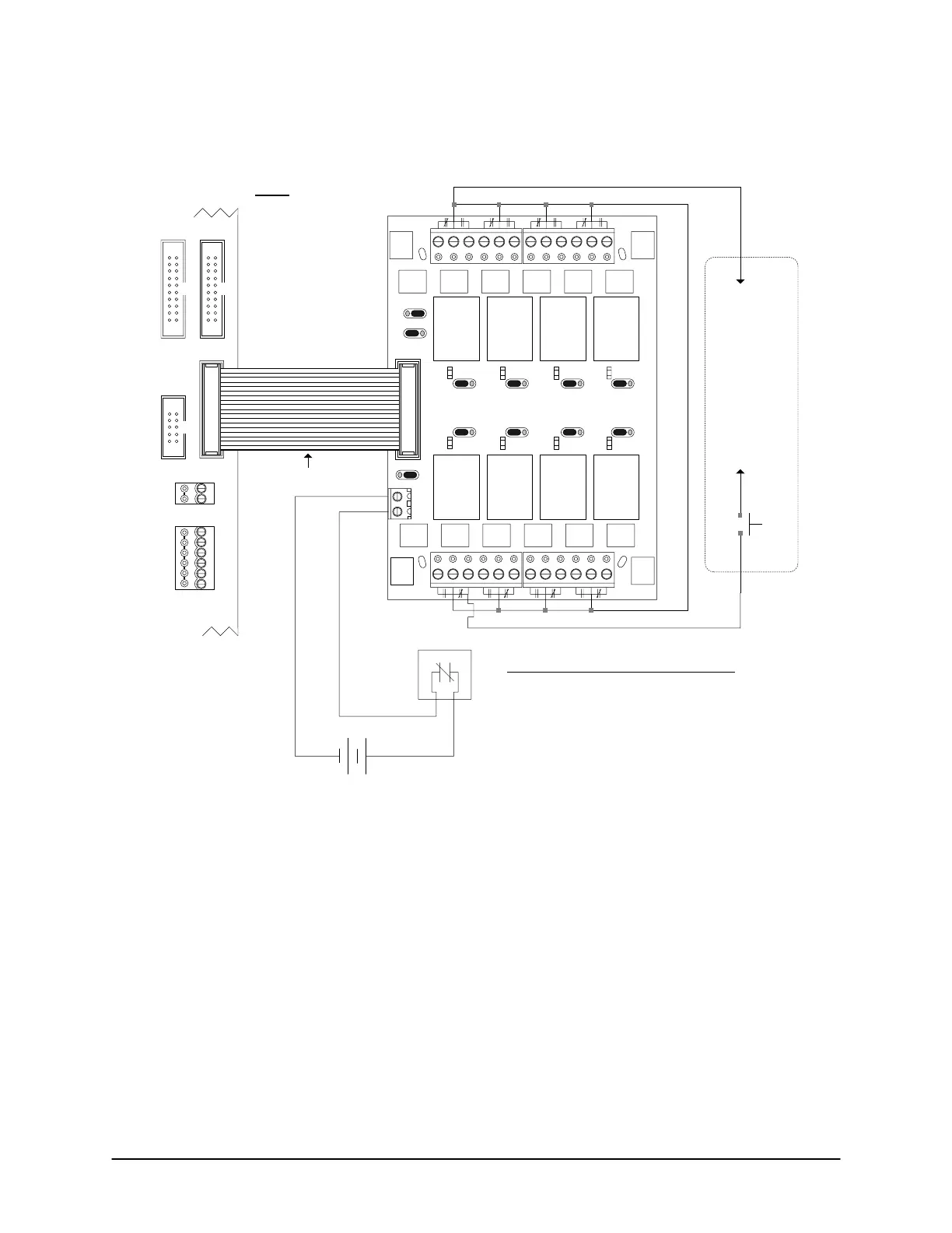
Figure 31 – Terminate Floor Wiring EC1500B
EC1500B
Control
Board
Cut View
+
-
OCB-8 ribbon cable
connects to CONTROL 1
(Floors 1 to 8)
Floor
Output
1
Floor
Output
2
Floor
Output
3
Floor
Output
4
Floor
Output
5
Floor
Output
6
Floor
Output
7
Floor
Output
8
J1 J2 J3 J4
J5J6J7
J8
12V
ACU EXT
PWR
Normal
Reversed
J1
to
J8
K1
K2 K3 K4
K5K6K7K8
GND
OCB-8
Current – 230 mA
Relays – Form C contacts
– 5 A / 30 VDC
– 10 A / 24 VAC
Fire Panel
trips on alarm
N.C.
connects to
floor call
button
connects to
common on
elevator
control circuit
elevator
button
EC1000 Control / Floor Output Assignments
Control 1 – OCB-8 Floor Outputs 1 – 8
Control 2 – OCB-8 Floor Outputs 9 – 16* (optional)
Control 3 – OCB-8 Floor outputs 17 – 24* (optional)
Control 4 – OCB-8 Floor Outputs 25 – 32* (optional)
Control 5 – OCB-8 Floor Outputs 33 – 40* (optional)
* OCB-8s must be purchased separately.
Ensure all elevator hardware complies with all fire code
regulations.
J9
AUX/RDR 12 V or
ACU 12 V
on DPS-15
Set J1 to J8 on Reversed & J9 on EXT PWR
Red stripe
CONTROL 2
RS-232 (COM4)
CTS
CONTROL 4
DTR
DCD
RD
TD
GND
TAMPER TB3
SWITCH
+
-
KI-00134E-07-11
 Loading...
