Keyscan Technical Guide (PC109x - 04.12)
130
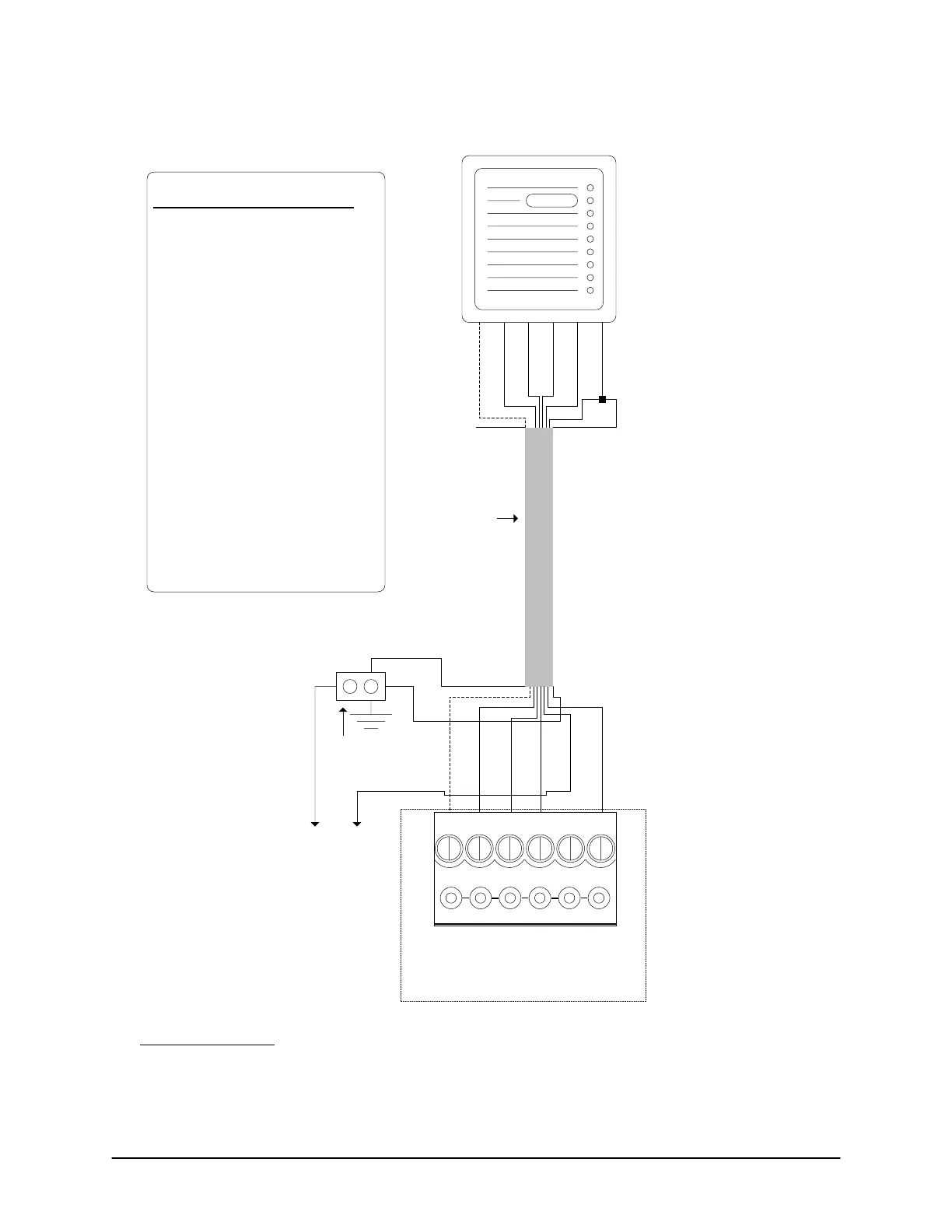
Figure 100 – HID 5375 Wiring
Pre-alert
(Yellow)
D1 (White)
D0 (Green)
Red
Black 1 & 2
Shield not
connected.
Isolate with
electrical tape.
Shield
ACU Ground
Lug
Red
+
VDC
PWR Red
Black
to
separate
DC power
supply
Black 1
6 conductors
shielded 18 AWG
Maximum - 500 ft
(152.4 m)
HID-5375 – DIP Switches/Jumpers
SW5
- switches 1 & 2 ON
- switches 3 to 8 OFF
SW2
- switch 1 ON
- switches 2 to 8 OFF
SW1
- switches 1 to 4 ON
- switches 5 to 8 OFF
P4
- jumper ON pins 1 & 2
P3
- jumper ON pins 1 & 2
P2
- jumper ON pins 1 & 2
P1
- jumper on pins 2 & 3
Reader terminal on control board
LED D1
WHT
D0
GRN
PWR
RED
GND
BLK
C1
(BEEP)
LED (Green)
Yellow (Beeper) used for pre-alert
otherwise isolate and tape back.
If connecting external sound device,
see Pre-Alert Relay Option or refer to
ACU cut sheet enclosed with panel
for ACU/OCB8 relay assignments.
D1 (White)
D0 (Green)
GND (Black 2)
LED
Pre-alert
(Yellow)
Note - If Pre-alert is
connected, the
reader cannot read
any HID 125 kHz-
compatible card
during the pre-alert
beep.
KI-00204E-07-11
Notes on HID 5375
HID 5375 operates at 12 VDC or 24 VDC. Refer to HID literature for correct jumper settings. If configured
for 12 VDC, do not connect to 24 VDC power supply, otherwise damage to the reader circuit board will
result.
 Loading...
