Keyscan Technical Guide (PC109x - 04.12)
25
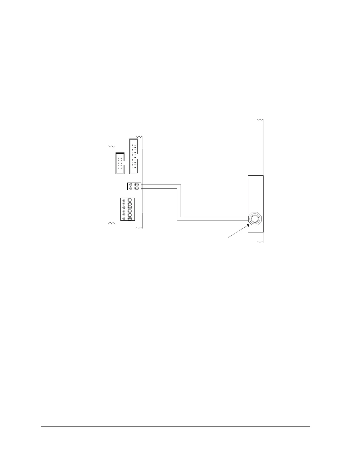
Enclosure Tamper Switch
Connect the yellow wires on the tamper switch to the TB3 terminal block on the control board as illustrated in
the diagram below. Please remember that this is a requirement for compliance with the following standards:
UL STD 294, CSA STD C22.2, CE, or FCC 15 Subpart B.
Figure 13 – Enclosure Tamper Switch Connected to TB3 Terminal
CONTROL 1
CTS
DTR
DCD
RD
TD
GND
RS-232 (COM4)
TAMPER TB3
SWITCH
+
-
Connect the yellow wires on the tamper
switch to TB3 terminal on the control board.
Protective
Cover
Metal
Enclosure
Tamper Switch
PC109x
Control Board
Cut View
KI-00116E-07-11
 Loading...
