196 Keysight E4980A/AL Precision LCR Meter
Measurement Procedure and Examples
Parallel/Series Circuit Mode
7-
Selecting Circuit Mode of Inductance
The following description gives some practical guidelines for selecting the
inductance measurement circuit mode.
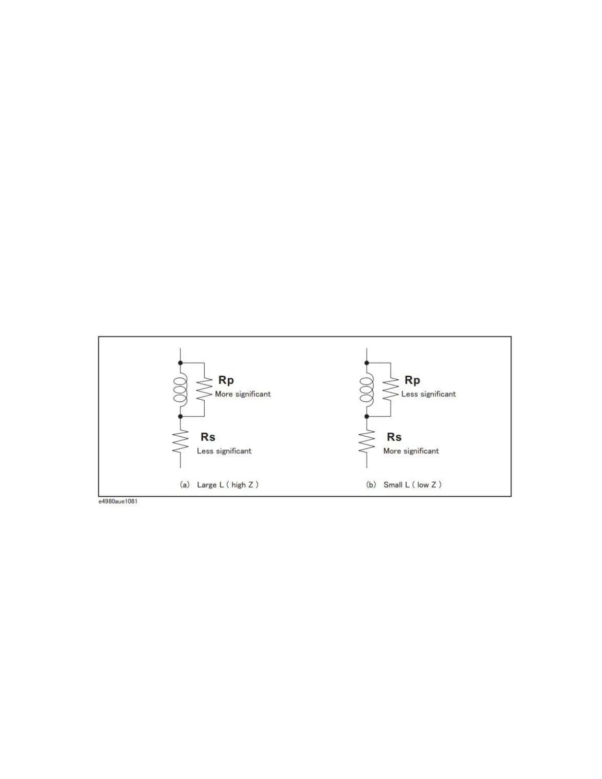
Figure 7-5 Inductance circuit mode selection
The following rule of thumb can be used for selecting the circuit mode
according to the impedance of the inductor.
For example, to measure a 1 mH inductor at 1 kHz (impedance will be approx.
6.3 ), the Ls-D or Ls-Q function is suitable.
Large Inductance (modeled by (a) in
Figure 7-5)
The reactance at a given frequency is relatively large (compared with that of a small
inductance), so the parallel resistance becomes more significant than the series
resistance. Therefore, a measurement in the parallel equivalent circuit mode (Lp-D,
Lp-Q, or Lp-G) is more suitable.
Small Inductance (modeled by (b) in
Figure 7-5)
Conversely, for low values of inductance the reactance becomes relatively small
(compared with that of a large inductance), so the series resistance component is more
significant. Therefore, the series equivalent circuit mode (Ls-D or Ls-Q) is more
suitable.
Below approx. 10 Use series circuit mode
Above approx. 10 k Use parallel circuit mode
Between above values Follow the manufacturer’s recommendation