-504 Keysight E4980A/AL User’s Guide
Scanner Interface
Electrical Characteristics of the Input/Output Signals
-
Electrical Characteristics of the Input/Output Signals
The electrical characteristics of the scanner interface I/O signals are described
below.
Channel Selection Input Signals
The /CH0 to /CH7 and /CH_VALID signals are optocoupled to isolate DC
inputs. Each signal is connected to the cathode of an LED in the optocoupler,
which is current driven, requiring 5 mA to 20 mA for proper operation. The
OFF-state voltage (high level) of each signal depends on the pull-up voltage
(EXT. DCV) used. EXT. DCV can be set from 5 V to 15 V. The selector switches
must be set according to the value of EXT. DCV used (Refer to
Table F-9).
External Trigger Input Signals
The EXT_TRIG signal is optocoupled to dc isolate the input. This signal is
connected to the cathode of an LED in an optocoupler which is current driven,
requiring 6.3 mA to 15 mA for proper operation. The OFF state voltage (high
level) of each signal depends on the pull-up voltage (EXT. DCV) used. EXT.
DCV can be set from 5 V to 15 V. The bit selector switches must be set
according to the value of EXT. DCV used (Refer to Table F-9).
Figure F-6 shows a diagram of channel selection input signals, and Figure F-7
shows a diagram of external trigger input signals.
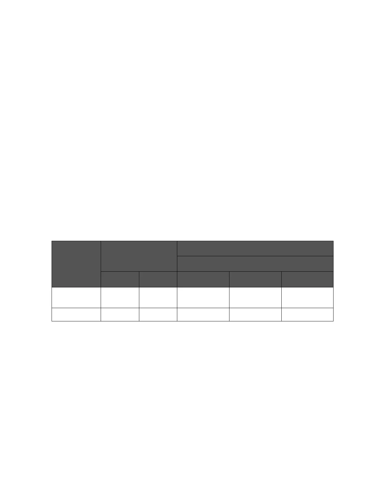
Table F-9 DC isolate input signal electrical characteristics
Signal Name Input Voltage Input Voltage (when low) (reference value)
Pull-up Supply Voltage EXT. DCV
Low High 5 V 12 V 15 V
/CH0 to /CH7
/CH_VALID
0 to 1 V EXT.DCV 9.0 mA 12.7 mA 16.2 mA
EXT_TRIG 0 to 1 V EXT.DCV 11.1 mA 10.5 mA 13.5 mA