-468 Keysight E4980A/AL User’s Guide
Handler Interface
Signal Line Definitions
-
12
13
/EXT_TRIG
/EXT_TRIG
Input An external trigger signal.
These signals are used in the external trigger mode. Triggering occurs when the pulse
reaches a rising edge.
14
15
EXT.DCV2
EXT.DCV2
Input External DC voltage.
Supplies voltage for DC isolation input signals (/EXT_TRIG, /KEY_LOCK) and DC
isolation output signals (/ALARM, /INDEX, /EOM).
To use the internal DC voltage, switch the settings with the jumper on the handler
interface board.
16
17
18
+5V
+5V
+5V
Output Internal DC voltage.
19 /PHI Output “Primary parameter beyond upper limit” signal.
This signal is output when the primary parameter has exceeded the upper limit for
bins 1 to 9.
20 /PLO Output “Primary parameter below lower limit” signal.
This signal is output when the primary parameter is below the lower limit for bins 1 to
9.
21 /SREJ Output “Secondary parameter out of limits” signal.
This signal is output when the secondary parameter is out the limits.
22 /READY_FOR_TRIGGER Output “Ready for trigger” signal. This signal is output while the instrument is ready to accept
trigger signals.
This means that it is output while the measurement screen is in the “trigger wait”
state. It is not output under any other conditions. Also, the signal is never output when
the trigger source is set to Internal Trigger.
23 RESERVED -- Not used.
24 /OVLD Output “Measurement failed” signal. This signal is output when the analog measurement
mechanism has failed to perform measurement (due to an overload). It is equivalent to
the /UNBAL signal of the 4284A.
25 /KEY_LOCK Input “Key lock” signal.
When this signal is input, the E4980A/AL's front panel keys are all disabled.
26 RESERVED -- Not used.
27
28
EXT.DCV1
EXT.DCV1
Input External DC voltage.
Supplies voltage for DC isolation signals (/BIN1 to /BIN9, /OUT_OF_BINS, /AUX_BIN,
/PHI, /PLO, /SREJ, /OVLD).
To use the internal DC voltage, switch the settings with the jumper on the handler
interface board.
29 /ALARM Output “Error detected” signal.
This signal is output when an instantaneous power failure has been detected. It is also
output when the handler interface board has been reset.
30 /INDEX Output “End of analog measurement” signal.
This signal is output when analog measurement is complete. This means that once the
handler has received this signal, the next DUT can be connected to the UNKNOWN
terminal. However, measurement data are not available until the /EOM signal is
output.
31 /EOM Output “End of measurement cycle” signal.
When this signal is output, the measurement data and sorting results are available.
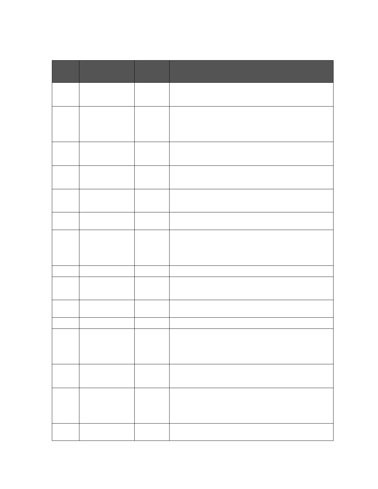
Table E-3 Pin layouts for the comparator
Pin
number
Signal name Signal
direction
Description