Keysight E4980A/AL User’s Guide -509
Scanner Interface
Setting Up the Scanner Interface Board
-
Step 6. Connect the flat cable to the scanner interface board, replace the scanner
interface board, and fix it onto place with the two screws.
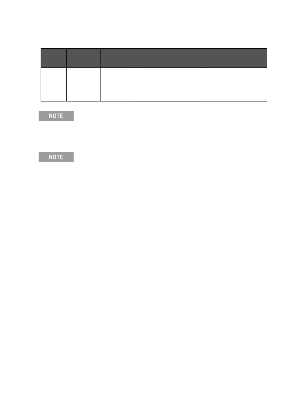
Table F-12 Setting Bit Switch (S2)
Bit Default Pull-up
Resistor
EXT. DCV Function
1-8 On 410
(When on)
5 V EXT.DCV 8 V /CH0 to /CH7
SW for input resistance
820
(When off)
8 V < EXT.DCV 15 V
Bit switches S1 and S2 can be identified by the labels “S1” and “S2” on the
scanner interface board.
Applying excessive force to the screws may break the tapped hole (less
than 0.98 N-m, 0.1 kgf-m).